How to measure capacitance and inductance
Devices for direct evaluation and comparison
Measuring devices for direct evaluation of the measured value of the capacitance include microfaradmeters, the operation of which is based on the dependence of the current or voltage in the alternating current circuit on the value included in it measured capacity… The capacitance value is determined on the dial scale.
Wider to measure capacitor parameters and inductors are used balanced bridges for alternating current, which allows to obtain a small measurement error (up to 1%). The bridge is powered by generators operating at a fixed frequency of 400-1000 Hz. Rectifier or electronic millivoltmeters, as well as oscillographic indicators, are used as indicators.
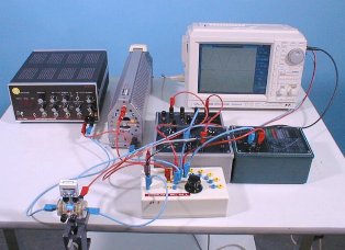
The measurement is made by balancing the bridge by sequentially adjusting its two arms. The reading is done by the extremities of the arms of those arms which balance the bridge.
As an example, consider the measuring bridges that form the basis of the EZ-3 inductance meter (Fig. 1) and the E8-3 capacitance meter (Fig. 2).
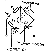
Rice. 1. Bridge circuit for measuring inductance
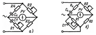
Rice. 2.Schematic of a low (a) and high (b) loss capacitance measurement bridge
With the balance of the bridge (Fig. 1), the inductance of the coil and its quality factor are determined by the formulas Lx = R1R2C2; Qx = wR1C1.
When balancing bridges (Fig. 2), the measured capacitance and loss resistance are determined by the formulas

Measurement of capacitance and inductance by the ammeter-voltmeter method
Resonance methods are widely used to measure small capacitances (no more than 0.01 — 0.05 μF) and high-frequency inductors in the range of their operating frequencies. Sensitive high-frequency devices that respond to current or voltage are used as resonant indicators.
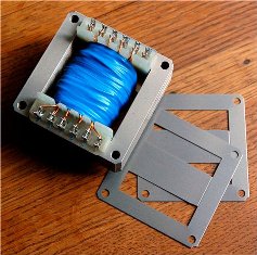
The ammeter-voltmeter method is used to measure relatively large capacitances and inductances when the measuring circuit is powered by a low-frequency source of 50-1000 Hz.
For measurement, you can use the diagrams in fig. 3.

Figure 3. Circuits for measuring large (a) and small (b) alternating current resistances
According to instrument readings, impedance

where

from these expressions it is possible to determine
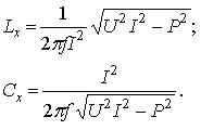
When it is possible to neglect the active losses in a capacitor or inductor, use the circuit of Fig. 4. In this case


Rice. 4. Circuits for measuring large (a) and small (b) resistances using the ammeter-voltmeter method
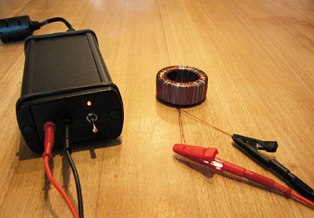
Measurement of the mutual inductance of two coils
Measurement mutual inductance two coils can be produced using the ammeter-voltmeter method (Fig. 5) and the series-connected coil method.
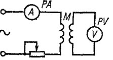
Rice. 5. Measurement of mutual inductance by the ammeter-voltmeter method
The value of mutual inductance measured by the ammeter-voltmeter method
 When measuring according to the second method, the inductance of two series-connected coils is measured with a common LAz and the counter LII turning on the coils. The mutual inductance is calculated by the formula
The inductance measurement can be done using one of the methods described above.
