How to determine induction motor slip during setup and operation
If the engine speed is significantly different from synchronously, is measured with a tachometer or tachogenerator, which is connected directly to the shaft of the electric motor, and the slip of the motor is determined by the formula S = (n1 — n2) / n1, where n1 = 60f / p — synchronous rotation frequency; n2 is the actual speed.
The advantages of this method of determining the slip of an electric motor: the speed of measurement and the ability to carry out both constant and variable speed. The disadvantages of this measurement method include the low accuracy of conventional tachometers (error 1–8%) and the difficulty of their calibration. In addition, the tachometer cannot be used when testing low-power electric motors, since the frictional losses in the tachometer mechanism represent a noticeable load.
To make various measurements, a hand-held tachometer is usually supplied with a set of interchangeable tips of various shapes and purposes, which are placed at the end of the roller (Fig. 1). The most widely used of these tips is the rubber cone, which is mounted in a metal cartridge. All of these tips are used to contact the pointed recess at the end of the shaft of the electric machine. The rubber center tip is used for high frequencies, the steel tip for low to medium frequencies.
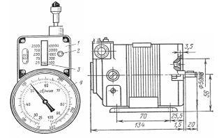 Rice. 1. General view of a centrifugal tachometer of type IO -10 and tachogenerator: 1 — scale; 2 — switch button; 3 — limit indicator; 4 — dial
If there is a hollow in the center of the shaft, an extension is used, which is placed on the tachometer shaft and the corresponding tip on the extension. In the absence or insufficiency of centers, a roller is used, which is pressed from the side surface (rubber ring) to the surface of the rotating shaft.
In accordance with the specific measurement conditions, select a fixture (extension tip). Before starting the measurement, remove grease, dirt, dust from the center of the groove or the surface of the shaft.
To measure the rotation speed of the electric motor, you must first set the necessary measurement limit of the tachometer. If the frequency measurement order is unknown, then the measurement should start from the highest limit to avoid damage to the tachometer.
The measurement should be carried out for a short time (3 — 5 s) by carefully pressing the tip of the tachometer against the rotating shaft with light pressure so that the axis of the tachometer shaft coincides with the axis of the measured shaft or, when using the roller, is parallel to it.
If the slip does not exceed 5%, the speed can be measured by the stroboscopic method using a neon lamp.
A diametrical line is drawn on the end of the motor shaft with chalk. While the engine is running, it is illuminated by a neon lamp powered by a network with the same frequency as the engine. The observer sees at the end of the shaft not a line, but a star slowly rotating against the direction of rotation of the shaft. The number of rays of the star depends on the number of poles of the motor and the position of the neon lamp. If the light from both electrodes of the lamp falls on the end of the shaft, the number of rays of the visible star is 2p. If the end of the shaft with the chalk line is illuminated by only one electrode, the number of rays of the visible star is equal to the number of poles.
During the time t (usually 30 s) measured by the stopwatch, the number of rays of the visible star m passing through the vertical position is counted. Since the number of rays of the visible star is 2p, the slip
where f1 is the frequency of the supply network of a neon lamp.
At f1 = 50 Hz.
Another variant of the stroboscopic method is the following. One of the disks is fixed on the motor shaft from the front side (Fig. 2). Assemble the chain (fig. 3). In a bipolar machine, a disc labeled 2p = 2 is fixed on the shaft and illuminated by a neon lamp with a patch electrode.
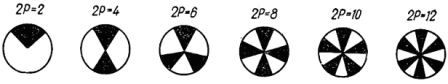
Rice. 2… Image of stroboscopic discs depending on the number of poles of the induction motor
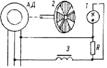
Rice. 3… Neon lamp switching scheme for stroboscopic method of slip detection: 1 — neon lamp, 2 — stroboscopic disc, 3 — induction coil
The rotor rotates asynchronously and lags behind the field, so the disc is seen slowly rotating in the opposite direction to the rotor's rotation.If during the time t m black sectors pass by a stationary point (an arrow fixed on a bearing), the slip value is given by the expression
The counting of sectors passing through a fixed point should not start from the moment the stopwatch starts, but from the next crossing of the mark.
To obtain a sharp image, a voltage must be applied to the lamp, the curve of which is shown in fig. 4… The lamp lights up when the voltage at its terminals reaches a value called the ignition threshold.
Rice. 4... Schematic for turning on a neon lamp to obtain a waveform with a sharp voltage: 1 — neon lamp; 2 — reactive coil with a highly saturated magnetic circuit with an inductive resistance X (the voltage drop across the resistances R and X are approximately the same)
Determination of motor slip using an induction coil. This method is based on monitoring the frequency of rotation of the dispersion fluxes of the rotor Fr (Fig. 5), which with a frequency proportional to the slip, cross the turns of the induction coil.
Rice. 5. Scheme for measuring the rotor slip of an asynchronous electric motor using an induction coil
A sensitive millivoltmeter (preferably with zero in the middle of the scale) is connected to the terminals of the coil; the coil is located at the end of the rotor shaft. By turning the coil in different directions, they find the position where the maximum oscillations of the instrument's arrow are observed. From the number of complete oscillations k at time t, the slip value is calculated

and at f = 50 Hz.

For the calculation, it is convenient to count 50 complete oscillations and note the time using a stopwatch. Then: .
As an induction coil, you can use a relay coil or a DC contactor with 10-20 thousand turns (or wind a coil with at least 3000 turns). To increase the magnetic flux, a core made of several strips of transformer steel is inserted into the coil. The induction coil method is very simple and suitable for all types of machines.
In asynchronous motors with a wound rotor, in addition to the methods described above, slip can be determined using a magnetoelectric ammeter connected to one of the rotor phases, and in the presence of non-switching resistance in the rotor circuit, using a voltmeter connected to the rotor rings. It is recommended to use instruments with a double-sided scale. The slip of an induction motor is calculated from the number of complete oscillations of the device needle, just as when using the induction coil method.