How are DC measurement bridges arranged and operated?
The device of single measuring bridges of direct current
A single direct current consists of three sample resistors (usually adjustable) R1, R2, R3 (Fig. 1, a), which are connected in series with the measured resistance Rx in the bridge circuit.
Power is applied to one of the diagonals of this circuit from the EMF source GB, and a highly sensitive galvanometer RA is connected to the other diagonal through the switch SA1 and the limiting resistance Ro.
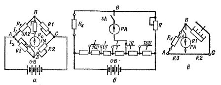
Rice. 1. Schemes of single direct current measuring bridges: a — common; b — with a smooth change in the arm ratio and a sharp change in the comparison arm.
The scheme works as follows. When power is supplied through resistors Rx, Rl, R2, R3, currents I1 and I2… These currents will cause a voltage drop across resistors Uab, Ubc, Uad and Udc.
If these voltage drops are different, then the potentials at points φa, φb and φc will not be the same.Therefore, if you turn on the galvanometer with the switch SA1, then a current equal to Azr = (φb — φd) / Po.
The task of the gauge is to balance the bridge, that is, to make the potentials of the points φb and φd equal, in other words, reduce the galvanometer current to zero.
To do this, they begin to change the resistances of resistors R1, R2 and R3 until the galvanometer current becomes zero.
At Azr = 0, it can be argued that φb = φd... This is possible only when the voltage drops Uab — Uad and type BC. = Udc.
Substituting into these expressions the voltage drop values Uad =I2R3, Ubc = I1R1, Udc = I2R2 and Uab = I1Rx, we get two equalities: I1Rx = I2R3, I1R1 = I2R2
Dividing the first equality by the second, we get RHC / R1 = R3 / R2 or RNS R2 = R1 R3
The last equality is the balancing condition of a single-bridge DC.
It follows that the bridge is balanced when the products of the resistances of the opposite arms are equal. Therefore, the measured resistance is determined by the formula Rx = R1R3 / R2
In real unitary bridges, either the resistance of the resistor R1 (called the comparator arm) or the ratio of the resistances R3/ R2.
There are measuring bridges in which only the resistance of the reference arm changes, and the ratio R3 / R2 remains constant. Conversely, only the ratio R3 / R2 changes, while the resistance of the comparison arm remains constant.
The most widespread are the measuring bridges, in which the resistance R1 changes smoothly and with jumps, usually multiples of 10, the ratio R3 / R2 changes (Fig. 1, b), for example, in the common measuring bridges P333.
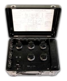
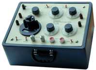
Rice. 2.Direct current measuring bridge P333
Each measuring bridge is characterized by a resistance measurement range from Rmin to Rmax. An important parameter of the bridge is its sensitivity. Sm = SGСcx, where Sg =da /dIg is the sensitivity of the galvanometer, Scx =dIG/dR — sensitivity of the circuit.
Substituting Sg and Scx in Sm, we get Sm = da/dR.
Sometimes the concept of the relative sensitivity of the measuring bridge is used:
Cm= da/ (dR / R).
where dR / R — the relative change in resistance in the measured arm, da — deflection angle of the galvanometer needle.
Depending on the design, a distinction is made between stock and linear (record) measuring bridges.
 In the shop-based measuring bridge, the arm resistances are made in the form of a plug or lever, multi-valued measures of electrical resistance (resistances), in record bridges, the comparison arm is made in the form of a shop resistance, and the deflection arms are in the form of a resistor , separated by a slider into two adjustable parts.
Permissible error, single measuring bridges of direct current have an accuracy class: 0.02; 0.05; 0.1; 0.2; 1.0; 5.0. The numerical value of the accuracy class corresponds to the largest permissible value of the relative error.
The error of a single DC bridge depends on the degree of commensurability of the resistances of the connecting wires and contacts with the measured resistance. The smaller the measured resistance, the greater the error. Therefore, double DC bridges are used to measure low resistance.
DC dual bridge device
The arms of the double (six-arm) measuring bridge are the measured resistance Rx (they are made with four clamps to reduce the influence of contact resistances and are connected to the network by a special device with four clamps), an example resistor Ro and two pairs of auxiliary resistors Rl, R2, R3, R4.
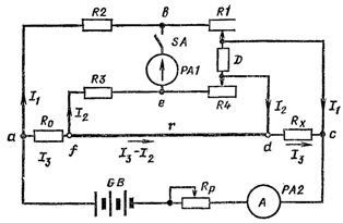
Rice. 3 Schematic of a dual measurement DC bridge
The balance of the bridge is determined by the formula:
Rx = Ro NS (R1 / R2) — (r R3 / (r + R3 + R4)) NS (R1 / R2 — R4 / R3)
This shows that if two arm ratios R1 / R2 and R4 / R3 are equal to each other, then the subtracted is zero.
Despite the fact that the resistances R1 and R4 moving the slider D are set the same, due to the spread of the parameters of the resistances R2 and R4, this is very difficult to achieve.
To reduce the measurement error, the resistance of the jumper connecting the reference resistor Ro and the measured resistance Rx should be taken as small as possible. A special calibrated resistor is usually attached to the device. r… Then the subtracted expression becomes practically zero.
The value of the measured resistance can be determined by the formula: Rx = Ro R1/R2
Dual DC metering bridges are designed to operate with variable arm ratios only. The sensitivity of the double bridge depends on the sensitivity of the zero pointer, the parameters of the bridge circuit and the value of the operating current. As the operating current increases, the sensitivity increases.
The most common are combined DC measurement bridges designed to work on single and double bridge schemes.