How to determine the start and end of the winding phases of an induction motor
 Line voltages and diagrams of the stator windings of an electric motor
If, for example, the passport of the electric motor indicates 220/380 V, this means that the electric motor can be connected to both the 220 V network (winding diagram - triangle) and the 380 V network (coil connection diagram - star) . The stator windings of the induction motor have six ends.
According to GOST, the windings of an asynchronous motor have the following designations: I phase — C1 (beginning), C4 (end), II phase — C2 (beginning), C5 (end), III phase — C3 (beginning), C6 (end).
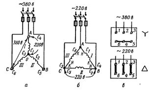
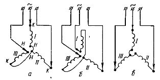
Rice. 1. Connection scheme of the windings of the asynchronous motor: a — in a star, b — in a triangle, c — implementation of the "star" and "delta" schemes on the terminal board.
If the mains voltage is 380 V, then the stator windings of the motor must be star-connected. At the same time, either all the beginnings (C1, C2, C3) or all the ends (C4, C5, C6) come together at a common point.A voltage of 380 V is applied between the ends of the windings AB, BC, CA. On each phase, that is, between points O and A, O and B, O and C, the voltage will be √Z times less: 380 / √Z = 220 V.
 Ways to connect electric motors
If the voltage is 220 V (with a 220/127 V voltage system, which is practically not found anywhere at the moment), the stator windings of the motor must be connected in a delta.
At points A, B and C, the beginning (H) of the previous winding is connected to the end (K) of the next winding and to the phase of the network (Fig. 1, b). If we assume that I phase is included between points A and B, between points B and C — II, and between points C and A — III phase, then with the "delta" scheme are connected: the beginning I (C1) with the end III (C6), start II (C2) with end I (C4) and start III (C3) with end II (C5).
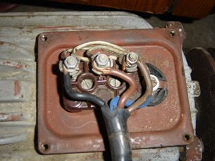
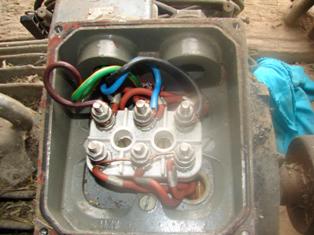
In some motors, the ends of the winding phases are brought out to the terminal board. According to GOST, the beginning and ends of the windings are brought out in the order as shown in figure 1, c.
If it is now necessary to connect the windings of the motor according to the «star» scheme, the terminals to which the ends (or the beginning) are brought out are short-circuited, and the phases of the network are connected to the motor terminals to which the beginning is brought out (or the ends).
When connecting the windings of the motor in a «delta», the clamps are connected vertically in pairs, and the mains phases are connected to the jumpers. Vertical jumpers connect start Iz to end III phases, start II to end Iz phases and start III to end phase II.
When determining the connection scheme of the windings, you can use the following table:
Voltage indicated in the passport of the electric motor, V
Mains voltage, V
127 220 380 127 / 220 triangle star — 220 / 380 — triangle star 380 / — — — triangle
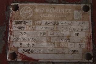
Electric motor passport
Determination of the matching terminals (beginning and end) of the phases of the stator winding.
The terminals of the motor stator windings usually have standard markings for metal lugs. However, these tips are lost. It then becomes necessary to identify the agreed conclusions. This is done in the following sequence.
First, with the help of a test lamp, determine the pairs of wires belonging to the individual phase windings (Fig. 2).
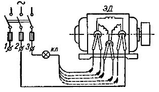
Rice. 2. Determination of phase windings using a test lamp.
One of the six terminals of the motor stator winding is connected to mains terminal 2, and one end of the test lamp is connected to the other terminal of mains 3. With the other end of the test lamp, touch each of the other five terminals of the stator windings in turn, until the lamp lights up. If the lamp lights up, then the two outputs connected to the network belong to the same phase.
At the same time, care must be taken not to short-circuit the coil cables. Each pair of pins is marked (eg by tying a knot).
Having determined the phases of the stator winding, proceed to the second part of the work - determining the agreed conclusions or "start" and "end". This work can be done in two ways.
1. Transformation method. A test lamp is switched on in one of the phases. The other two phases are connected in series and comprise the mains phase voltage.
If it turns out that these two phases are included in such a way that the conditional "end" of one phase is also connected to the conditional "beginning" of the other at point O (Fig. 3, a), then the magnetic note ∑ Ф crosses the third coil and induces an EMF in it.
The lamp will indicate the presence of an EMF with a slight glow. If the glow is invisible, then a voltmeter with a scale up to 30 — 60 V should be used as an indicator.
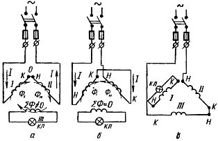
Rice. 3. Determination of the beginning and end of the phase windings of the motor by the method of transformation
If, for example, conditional "ends" of the coils meet at point O (Fig. 3, b), then the magnetic fluxes of the coils will be directed against each other. The total flux will be close to zero and the lamp will not light (the voltmeter will read O). In this case, conclusions belonging to any of the phases must be canceled and re-enabled.
If the lamp lights up (or the voltmeter shows some voltage), then the ends should be marked. On one of the conclusions that met at a common point O, they put a label marked H1 (beginning of I phase), and to the other output - K3 (or K2).
Labels K1 and H3 (or H2) are placed on the conclusions that are in common nodes (tied in the first part of the work) with H1 and K3, respectively.
To determine the matched conclusions of the third winding, the circuit shown in Figure 3, c. The lamp is switched on in one of the phases with the terminals already indicated.
2. Phase selection method. This method of determining the matching terminals (start and end) of the phases of the stator winding can be used for low power motors — up to 3 — 5 kW.
Rice. 4. Determining the «beginning» and «end» of the winding by selecting the «star» circuit.
Once the terminals of the individual phases have been determined, they are randomly connected to star (one terminal of the phase is connected to the mains and one terminal at a time is connected to a common point) and the motor is connected to the mains. If all conditional «starts» or all «ends» hit the common point, then the engine will work normally.
But if one of the phases (III) turned out to be "reversed" (Fig. 4, a), then the motor hums loudly, although it can rotate (but it can easily be stopped). In this case, the conclusions of one of the windings randomly (for example, I) must be exchanged (Fig. 4, b).
If the motor hums again and does not work well, then the phase should be turned on again, as before (as in scheme a), but turn on another phase — III (Fig. 3, c).
If the motor hums after this, then this phase should also be set as before, and the next phase should be reversed — II.
When the engine starts to work normally (Fig. 4, c), all three wires that are connected to a common point should be marked in the same way, for example, "ends" and the opposite ones - "beginning". After that, you can assemble the working diagram indicated in the engine passport.