Determination of the transformation ratio of power transformers
The transformation factor (K) is the ratio of the HV winding voltage to the LV winding voltage when the transformer is no-load:
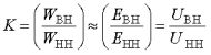
For three-winding transformers, the transformation factor is the ratio of the winding voltages HV / MV, HV / LV and MV / LV.
 The value of the transformation coefficient allows you to check the correct number of turns of the transformer windings, therefore it is determined for all branches of the windings and for all phases. These measurements, in addition to checking the transformation ratio itself, make it possible to check the correct installation of the voltage switch in the corresponding steps, as well as the integrity of the windings.
 If the transformer is installed without opening and at the same time several taps are not available for measurements, the transformation factor is determined only for the available taps.
When testing three-winding transformers, it is sufficient to check the transformation ratio for two pairs of windings, and it is recommended to make measurements on those windings for which the short-circuit voltage is the smallest.
In the passport of each transformer, the nominal voltages of the two windings associated with the idle mode are indicated. Therefore, the nominal transformation ratio can be easily determined from their ratio.
The measured transformation ratio of all stages of the tap changer shall not differ by more than 2% from the transformation ratio of the same tap of other phases either from the nominal data or from the data of previous measurements. In case of a more significant deviation, its reason should be clarified. In the absence of a short circuit in a turn, the transformer can be put into operation.
The transformation factor is determined by the following methods:
a) two voltmeters;
b) AC bridge;
c) direct current;
d) example (standard) transformer, etc.
 It is recommended that the transformation coefficient be determined by the method of two voltmeters (Fig. 1).
A schematic diagram for determining the transformation ratio by the method of two voltmeters for single-phase transformers is given in Fig. 1, a. The voltage applied to the two windings of the transformer is measured simultaneously by two different voltmeters.
When testing three-phase transformers, the line voltages corresponding to the terminals of the same name of the two tested windings are measured simultaneously.The applied voltage must not exceed the rated voltage of the transformer and be too low so that the measurement results cannot be affected by errors due to voltage loss in the windings from the no-load current and the current caused by connecting the measuring device to the terminals of the secondary winding.
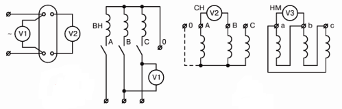
Rice. 1. The method of two voltmeters for determining the transformation ratios: a — for two-winding and b — three-winding transformers
The supplied voltage should be from one (for high-power transformers) to several tens of percent of the nominal voltage (for low-power transformers) if tests are conducted to verify the passport data of the transformers.
In most cases, the voltage is supplied to the transformer from the 380 V network. If necessary, the voltmeter is connected through a voltage transformer or switched on with an additional resistance. Accuracy classes of measuring devices — 0.2–0.5. It is allowed to connect the voltmeter V1 to the supply wires, and not to the bushings of the transformer, if this does not affect the accuracy of the measurement due to the voltage drop in the supply wires.
When testing three-phase transformers, a symmetrical three-phase voltage is applied to one winding and the line-to-line voltages of the terminal lines of the primary and secondary windings are measured simultaneously.
When measuring phase voltages, it is allowed to determine the transformation coefficient from the phase voltages of the respective phases. In this case, the transformation ratio is checked with single-phase or three-phase excitation of the transformer.
If the transformation factor is set at the factory, then it is recommended to measure the same voltages during installation. In the absence of a symmetrical three-phase voltage, the transformation ratio of three-phase transformers with a connection diagram of D / U or U / D winding can be determined using phase voltages with an alternating short circuit of the phases.
For this purpose, one phase of the winding (e.g. phase A) connected in delta is short-circuited by connecting two corresponding line terminals of this winding. Then, with single-phase excitation, the transformation coefficient of the remaining free pair of phases is determined, which with this method should be equal to 2 Kph for the D / U system when it is fed from the star side (Fig. 2) or Kph / 2 for the U / D circuit when fed from the delta side, where Kf is the phase transformation coefficient (Fig. 3).
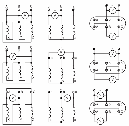
Rice. 2. Determination of the transformation ratios of a transformer connected according to the D / U scheme, with asymmetric three-phase voltage: a — the first; b — second and c — third dimension
In a similar way, measurements are made with short-circuited phases B and C. When testing transformers with three windings, it is enough to check the transformation coefficient for two pairs of windings (see Fig. 1, b).
If the transformer has a zero and all the beginnings and ends of the windings are accessible, then the transformation ratio can be determined for phase voltages. The transformation ratio for the phase voltages is checked with single-phase or three-phase excitation of the transformer.
For transformers with on-load switches, the difference in the transformation ratio should not exceed the value of the control step. The transformation ratio during acceptance tests is determined twice - the first time before installation, if the passport data is missing or in doubt, and the second time immediately before commissioning when the idle characteristic is accepted.
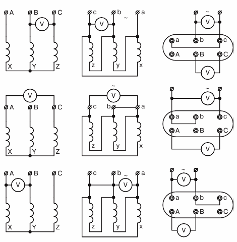
Rice. 3. Determination of the transformation ratios of the transformer connected according to the U / D scheme, with asymmetric three-phase voltage: a — the first; b — second and c — third dimension
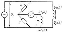
Rice. 4. Schematic diagram of a universal device of the UIKT-3 type
To speed up the measurement of the transformation ratio, a universal device of the UIKT-3 type is used, with which it is possible to measure power transformation ratios and measure current and voltage transformers without using an external source of alternating current. Simultaneously with the measurement of the transformation coefficient, the polarity of the primary and secondary windings is determined. The measurement error should not exceed 0.5% of the measured value.
The principle of operation of the device is based on comparing the voltages induced in the secondary and primary windings of the transformer with the voltage drop at known resistances (Fig. 4). The comparison is made by bridge circuit.