Dielectric loss tangent, dielectric loss index measurement
 Dielectric loss is the energy dissipated in an insulating material under the influence of an electric field on it.
The ability of a dielectric to dissipate energy in an electric field is usually characterized by an angle of dielectric losses, and a tangent of an angle dielectric loss... In the test, the dielectric is considered to be the dielectric of a capacitor, the capacitance and angle of which are measured. δ, complementing the phase angle between current and voltage in the capacitive circuit to 90 °. This angle is called the dielectric loss angle.
With an alternating voltage, a current flows in the insulation, which is in phase with the applied voltage at an angle ϕ (Fig. 1), less than 90 degrees. e-mail at a small angle δ, due to the presence of active resistance.
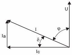
Rice. 1.Vector diagram of currents through a dielectric with losses: U — voltage on the dielectric; I is the total current through the dielectric; Ia, Ic — active and capacitive components of the total current, respectively; ϕ is the phase shift angle between the applied voltage and the total current; δ is the angle between the total current and its capacitive component
The ratio of the active component of the current Ia to the capacitive component Ic is called the tangent of the dielectric loss angle and is expressed as a percentage:
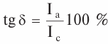
In an ideal dielectric without losses, the angle δ = 0 and, accordingly, tan δ = 0. Wetting and other insulation defects cause an increase in the active component of the dielectric loss current and tgδ. Since in this case the active component grows much faster than the capacitive one, the tan δ indicator reflects the change in the insulation state and losses in it. With a small amount of insulation, it is possible to detect developed local and concentrated defects.
Dielectric loss tangent measurement
To measure capacitance and dielectric loss angle (or tgδ), the equivalent circuit of a capacitor is represented as an ideal capacitor with an active resistance connected in series (series circuit) or as an ideal capacitor with an active resistance connected in parallel (parallel circuit).
For a series circuit, the active power is:
P = (U2ωtgδ)/(1 + tg2δ), tgδ = ωCR
For a parallel circuit:
P = U2ωtgδ, tgδ = 1 /(ωСR)
where B. — capacitance of an ideal capacitor; R — active resistance.
Sense angle of dielectric losses usually does not exceed hundredths or tenths of unity (therefore angle of dielectric losses usually expressed as a percentage), then 1 + tg2δ≈ 1, and losses for series and parallel equivalent circuits P = U2ωtgδ, tgδ = 1 /( ωCR)
The value of losses is proportional to the square of the voltage and frequency applied to the dielectric, which must be taken into account when choosing electrical insulating materials for high voltage and high frequency equipment.
With an increase in the voltage applied to the dielectric to a certain value UО, the ionization of gas and liquid inclusions present in the dielectric begins, while δ begins to increase sharply due to additional losses caused by ionization. At U1, the gas is ionized and reduced (Fig. 2).
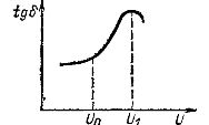
Rice. 2. Ionization curve tgδ = f (U)
Mean dielectric loss tangent measured at voltages lower than UО (typically 3 — 10 kV). The voltage is chosen to facilitate the test device while maintaining sufficient instrument sensitivity.
Meaning the tangent of dielectric losses (tgδ) normalized for a temperature of 20 ° C, therefore the measurement should be carried out at temperatures close to the normalized ones (10 — 20 ОС). In this temperature range, the change in dielectric losses is small, and for some types of insulation, the measured value can be compared without recalculation with the normalized value for 20 ° C.
In order to eliminate the influence of leakage currents and external electrostatic fields on the measurement results of the test object and around the measuring circuit, protective devices in the form of protective rings and screens are installed.The presence of grounded shields causes stray capacitances; to compensate for their influence, the protection method is usually used — voltage adjustable in value and phase.
They are the most common bridge measuring circuits capacitance tangent and dielectric losses.
Local defects caused by conductive bridges are best detected by measuring the DC insulation resistance. The measurement of tan δ is performed with AC bridges of types MD-16, P5026 (P5026M) or P595, which are essentially capacitance meters (Schering bridge). A schematic diagram of the bridge is shown in Fig. 3.
In this scheme, the parameters of the isolation structure corresponding to the equivalent circuit with a series connection of a lossless capacitor C and a resistor R are determined, for which tan δ = ωRC, where ω is the angular frequency of the network.
The measurement process consists in balancing (balancing) the bridge circuit by successively adjusting the resistance of the resistor and the capacitance of the capacitor box. When the bridge is in equilibrium, as indicated by the measuring device P, the equality is satisfied. If the value of the capacitance C is expressed in microfarads, then at the industrial frequency of the network f = 50 Hz we will have ω = 2πf = 100π and therefore tan δ% = 0.01πRC.
A schematic diagram of the P525 bridge is shown in Fig. 3.
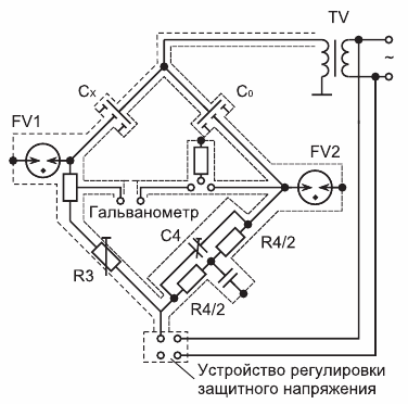
Rice. 3. Schematic diagram of the AC measuring bridge P525
Measurement is possible for voltages up to 1 kV and above 1 kV (3-10 kV), depending on the insulation class and capacity of the object. A voltage measuring transformer can serve as a power source. The bridge is used with an external air capacitor C0.A schematic diagram of the inclusion of the equipment when measuring tan δ is shown in Fig. 4.
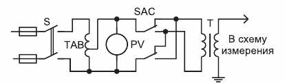
Rice. 4. Connection diagram of the test transformer when measuring the tangent of the angle of dielectric losses: S — switch; TAB — autotransformer adjustment; SAC — Polarity Switch for Test Transformer T
Two bridge switching circuits are used: the so-called normal or straight, in which the measuring element P is connected between one of the electrodes of the tested insulating structure and the ground, and inverted, where it is connected between the electrode of the tested object and the high-voltage terminal of the bridge. The normal circuit is used when both electrodes are isolated from the ground, reversed - when one of the electrodes is firmly connected to the ground.
It must be remembered that in the latter case the individual elements of the bridge will be under full test tension. Measurement is possible at voltages up to 1 kV and above 1 kV (3-10 kV), depending on the insulation class and capacity of the object. A voltage measuring transformer can serve as a power source.
The bridge is used with an external reference air capacitor. The bridge and the necessary equipment are placed in close proximity to the test site and a fence is installed. The wire that leads from the test transformer T to the model capacitor C, as well as the connecting cables of the bridge P, which are under voltage, must be removed from grounded objects by at least 100-150 mm. The transformer T and its regulating device TAB ( LATR) must be at a distance of at least 0.5 m from the bridge.The bridge, transformer and regulator housings, as well as one terminal of the transformer secondary winding, must be earthed.
The indicator tan δ is often measured in the operational switchgear area, and since there is always a capacitive connection between the test object and the switchgear elements, the influencing current flows through the test object. This current, which depends on the voltage and phase of the influencing voltage and the total capacitance of the connection, can lead to an incorrect assessment of the insulation condition, especially on objects with a small capacitance, in particular bushings (up to 1000-2000 pF).
Balancing the bridge is done by repeatedly adjusting the elements of the bridge circuit and the protective voltage, for which the balance indicator is included either in the diagonal or between the screen and the diagonal. The bridge is considered balanced if there is no current through it with the simultaneous inclusion of the balance indicator.
At the time of bridge balancing
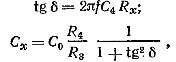
Gde f is the frequency of the alternating current supplying the circuit
° Cx = (R4 / Rx) Co
Constant resistance R4 is chosen equal to 104/π Ω In this case tgδ = C4, where the capacitance C4 is expressed in microfarads.
If the measurement was made with a frequency f 'other than 50Hz, then tgδ = (f '/ 50) C4
When the dielectric loss tangent measurement is performed on small sections of cable or samples of insulating materials; due to their low capacity, electronic amplifiers are necessary (for example, of the F-50-1 type with a gain of about 60).Note that the bridge takes into account the loss in the wire connecting the bridge to the test object, and the measured dielectric loss tangent value will be more valid at 2πfRzCx, where Rz — resistance of the wire.
When measuring according to an inverted bridge scheme, the adjustable elements of the measuring circuit are under high voltage, therefore the adjustment of the bridge elements is carried out either at a distance using insulating rods, or the operator is placed in a common screen with measuring elements.
The tangent of the dielectric loss angle of transformers and electrical machines is measured between each winding and the housing with grounded free windings.
Electric field effects
Distinguish between electrostatic and electromagnetic effects of an electric field. Electromagnetic influences are excluded by full shielding. The measuring elements are placed in a metal housing (e.g. bridges P5026 and P595). Electrostatic influences are created by live parts of switchgear and power lines. The influencing voltage vector can occupy any position with respect to the test voltage vector.
There are several ways to reduce the influence of electrostatic fields on the results of tan δ measurements:
-
switching off the voltage generating the influencing field. This method is the most effective, but not always applicable in terms of energy supply to consumers;
-
withdrawing the test object from the area of influence. The goal is achieved, but transporting the object is undesirable and not always possible;
-
measuring a frequency other than 50 Hz. It is rarely used because it requires special equipment;
-
computational methods for error exclusion;
-
a method of compensation of influences, in which an alignment of the vectors of the test voltage and the EMF of the affected field is achieved.
For this purpose, a phase shifter is included in the voltage regulation circuit and, when the test object is switched off, the bridge balance is achieved. In the absence of a phase regulator, an effective measure can be to supply the bridge from this voltage of the three-phase system (taking into account the polarity), in which case the measurement result will be minimal. It is often sufficient to carry out the measurement four times with different polarities of the test voltage and a bridge galvanometer connected; They are used both independently and to improve the results obtained by other methods.