Electrical equipment and automation of electrolysis plants
 All electrodes in electrolysis baths are usually connected in parallel, so that the current of the electrolyzer consists of the sum of the currents of individual pairs of electrodes: on the contrary, the voltage in the bath is equal to the voltage in the pairs of electrodes. The electrolysis baths, in turn, are connected in series, so that the total voltage of the installation reaches hundreds of volts. An exception is water decomposition installations made on the principle of a filter press, where all electrodes are connected in series.
Due to the fact that the currents in the electrolyzed plants and the sizes of the plants are large, the current lead system is quite branched, with a large number of contacts.
In fig. 1 shows a busbar diagram for an aluminum electrolysis bath. As you can see it is very complex, providing bi-directional power supply through powerful bus packs and the use of flexible thermal expansion compensators.In addition, in case it is necessary to disconnect the baths during repairs, jumpers are provided that connect the cathode packs of two adjacent baths, thereby removing one of them.
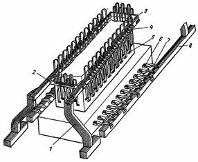
Rice. 1. Busbar for an aluminum electrolysis bath with one continuous anode and side current supply: 1 — anode riser, 2 — anode busbar, 3 — compensation busbar, 4 — flexible anode busbars, 5 — pin busbar contact, 6 — cathode busbar rod , 7 — flexible cathode bus, 8 — package cathode bus.
Aluminum and copper are used as material for rails, less often iron. Economic current density at electrolysis is 0.3 — 0.4 for aluminum busbars, 1.0 — 1.3 for copper busbars, 0.15 — 0.2 A / mm2 for steel and cast iron busbars.
The cross-section of the tires is checked for tension loss (no more than 3%), for heating (maximum temperature 70 ° C at an ambient temperature of 25 ° C) and for mechanical strength. Fixed contact connections are made by pressure (the tires are compressed between two cast steel plates, tightened with bolts) or welded. The plug contacts are bolted. Wedge or eccentric clamps are more reliable and convenient.
 Because of their higher power, electrolysis plants are usually fed from a high-voltage network, and special step-down transformers are used to match the supply voltage to the plants' voltage by supplying conversion units to convert three-phase alternating current to direct current.
Semiconductor rectifiers with smooth voltage regulation are used to power electrolysis plants with high power, because their efficiency is high (98 — 99%), they are more reliable and durable, easy to maintain, constantly ready for operation, silent and no toxic emissions.
When creating powerful electrolysis plants, it is necessary to include semiconductor valves in parallel, and sometimes in series, which causes difficulties due to a certain dispersion of their characteristics. To equalize the current distribution between the valves in parallel connection and the voltage in series, special circuit solutions are used.
Since semiconductor valves are not able to withstand significant current and voltage overloads, special protective devices are used that short-circuit the valves in case of failure and turn them off when a dangerous increase in voltage or operating current occurs.
 Regulation of the rectified voltage in installations with semiconductor diodes is only possible on the AC side. For this, switching of the voltage steps of the main step-down transformer or a special control transformer with a remote step switch is used. A saturation reactor is included in each arm of the rectifier bridge for smooth voltage regulation.
Valve arrangement is usually carried out in cabinets manufactured for currents of 13,000 and 25,000 A and for rectified voltage of 300 — 465 V. Converting substations feeding electrolysis plants are completed by the cabinets. Cooling of rectifier cabinets can be air or water.
Automatic adjustment of the converter units can be done in three ways: for constant voltage, for constant power, for constant current.
DC voltage regulation also provides constant current for processes where there are no anode effects. For aluminum electrolysis plants, such a system is not satisfactory, because with the appearance of anodic effects, the current in a series of baths decreases and the productivity of the baths decreases, especially with simultaneous anodic effects in several baths. In this case, not only the productivity of a series of baths can drop by 20 — 30%, but also the thermal mode of operation of the electrolysis baths is disturbed.
 In constant power regulation, the latter is maintained by a constant regulator; in the above case the series current drops but less than in the previous case as the regulator increases the voltage. With this regulation, there are no changes in energy consumption, which is desirable for the power system, but requires a voltage margin at the conversion substation.
DC regulation is the best in terms of meeting process requirements. However, with such regulation, in the event of a voltage drop in the supply network or the appearance of an anode effect, the regulator increases the supply voltage and energy consumption increases. Therefore, this control system requires both voltage and power reserves in the converter substation (typically within 7-10%).
Recently, work has begun on the use of parametric current sources for powering electrolysis plants, in which an anode effect occurs, which automatically stabilizes the alternating current regardless of changes in its resistance.
Usually, electrolysis baths are installed along the axis of the building body in two or four rows, and the power substation is connected to the body of the bath through bus ducts in bus ducts or by ramps. Inside the housing, the busbars are located in busbar channels on both sides of the cells.
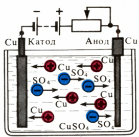
Diagram of movement of ions during copper electrolysis Electrolyte - copper sulfate solution is poured into a vessel and two copper plates (electrodes) are lowered into it. The processes occurring during electrolysis are discussed in the articles What is electrolysis and Electrolysis - calculation examples.