Testing capacitors
 Measurement of insulation resistance of capacitors. When testing power capacitors, the insulation resistance is measured with a megohmmeter for a voltage of 2500 V between the terminals and relative to the capacitor case. Insulation resistance and ratio are not standardizedI am.
Trial period capacitors increased voltage of the industrial frequency of dielectric strength of the insulation. Duration of application of the test voltage 1 min. The test is performed on the insulation between the conductors of the capacitor and between the conductors and the housing. The test voltage is taken according to the table. 1.
Table 1. Test voltages of capacitors for reactive power compensation
Test types Test voltage, kV, at operating voltage, kV 0.22 0.38 0.50 0.66 6.30 10.5 Between capacitor plates 0.42 0.72 0.95 1.25 11.8 20 With respect to the condenser case 2.1 2.1 2.1 5.1 15.3 21.3
The power of the test transformer when testing the insulation between the terminals of the capacitors should be relatively large and can be determined by the formula:
Pisp = ωCU2x 10 -9
where P.internet provider — power consumption, kVA, C is the capacitance of the capacitor, pF, U — test voltage, kV, ω — the angular frequency of the test voltage equal to 314 in 50 Hz.
The increase and decrease of voltage should be done smoothly. In the absence of a test transformer of sufficient power, the alternating current tests may be replaced by a rectified voltage test equal to twice that specified in the table. 1 stress.
Industrial frequency increased voltage tests shall not be performed in relation to the insulation case of capacitors designed to compensate for reactive power having a terminal connected to the enclosure.
After the test, the capacitor bank must be reliably discharged. Discharge is initially accomplished by current limiting and then short-circuiting.
Capacitance measurement is mandatory for capacitors designed to compensate reactive power for voltages of 1000 V and above. The measurements should be carried out at a temperature of 15 — 35 ° C. Capacitance measurement of capacitors produced using AC bridges, microfaradometer, ammeter and voltmeter method (Fig. 1, a) or using two voltmeters (Fig. 1, b).
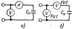
Rice. 1. Schemes for measuring the capacity of a capacitor: a — by the ammeter and voltmeter method, b — by the two voltmeter method.
The capacity measured with an ammeter and a voltmeter is calculated by the formula:
Cx = (I x 106) / ωU,
where Cx is the capacitance of the capacitor, μF, I — measured current, A, U — voltage of the capacitor, V, ω — the angular frequency of the network equal to 314 at 50 Hz.
When measuring the capacity of capacitors with an ammeter and a voltmeter, the voltage must be sinusoidal. With a distorted current waveform due to higher harmonic components, the measurement error increases significantly. Therefore, it is recommended to make measurements at linear rather than phase-neutral network voltage and to include in the circuit in series with the capacitor an active resistance equal to approximately 10% of the reactance of the measured capacitor.
When measuring with two voltmeters:
Cx = 106 / ωRtgφ,
R — internal resistance of the voltmeter, Ohm, tgφ — is determined by the cosine of the angle φ phase shift between the voltages of the voltmeter U1 and U2, cosφ = U2 / U1.
In single-phase capacitors, the capacity is measured between the terminals, in three-phase capacitors - between each pair of short-circuited terminals and the third terminal according to the table. 2.
Table 2. Schemes for measuring the capacity of three-phase capacitors
Short circuit Measure the capacitance between the terminals Designation of the measured capacitance 2 and 3 1 — (2 and 3) C (1 — 2.3) 1 and 3 2 — (1 and 3) C (2 — 1.3) 1 and 2 3 — (1 and 2) C (3 — 1.2)
No capacitance measurement is performed between the wires and the box. Pin numbering is arbitrary.
The capacitance of each phase of a delta-connected capacitor is determined from the measurement data from the equations:
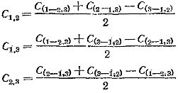
Full capacitor capacity:
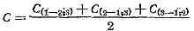
The measured capacities should not differ from the passport data by more than 10%.
Testing the capacitor bank by turning on the mains operating voltage three times and measuring the current in each phase of the battery. When the capacitor bank is turned on, no abnormal phenomena should be observed (automatic shutdown, blown fuses, noise and crackling in the tanks, etc.). The currents in the different phases of the battery should not differ from each other by more than 5%. It is forbidden to include capacitors for a voltage higher than 110% of the nominal.