Control of the insulation of the distribution elements
 One of the most important types of tests after installation or major repair of the switchgear is to determine the general average level of the insulation condition of the switchgear elements and to identify the weak places in the insulation (local defects).
The most common and simple method of monitoring the insulation of both primary and secondary switching devices is to measure the voltage-rectified insulation resistance value using a megohmmeter. They are good at identifying weak points in the insulation of equipment, which are accompanied by a sharp decrease in the insulation resistance of the phases to each other or to earth. In the absence of obvious damage and connections, measurement by this method gives an idea of the average condition of the insulation, mainly in terms of its moisture and contamination.
 The assessment of the state of insulation of the individual elements of the device according to the measurement data should be compared with the measurement during the previous current repair, by comparing the readings for individual phases of individual elements of the same type with each other. A sharp decrease in the insulation resistance, for example, of one insulator compared to another indicates the presence of a defect in it.
Measurement of insulation resistance with megohmmeter can be carried out only after removing the operating voltage and capacitive charge from the equipment or elements of the switchgear.
For suspended and supporting insulation of substations, a method of measuring the voltage distribution on the insulation under operating conditions using a special rod is used. The stress distribution on the surface of solid insulation for a given type of insulation is quite definite and can be represented by a characteristic curve. When one of the insulating elements is damaged, the voltage distribution changes: it decreases on the damaged element and increases accordingly on the healthy ones.
As an example, the figure shows the voltage distribution curves for the 110 kV string for suitable insulators and for the case of failure of the fourth insulator. The insulator must be replaced if the magnitude of the voltage applied to it as measured by the rod. reduced compared to the voltage falling on a suitable insulator, not less than 1.5 — 2 times.
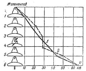
Results of measurements of voltage distribution strings of insulators: 1 — for healthy insulators, 2 — in case of failure of the fourth insulator from above.
For high voltage filled with oil, mastic and Bakelite insulators and bushings, the general condition of the insulation depends on the amount of dielectric losses. However, a more convenient indicator characterizing the average level of the insulation condition of the bushings is no loss (depending on the size of the insulator) and the tangent of the loss angle, which is practically equal to the ratio of active leakage current to capacitive current (tgδ = Aza/Azv), This value is measured with special instruments (bridges).
 Dielectric loss angle measurement makes it possible to observe the aging process of such hygroscopic insulation as Bakelite, paper, etc., in which air gaps are formed, which promotes the penetration of moisture into the insulation.
These and all other changes leading to a decrease in the quality of this insulation lead to an increase in dielectric losses. Therefore, the control of the average level of the insulation condition by the method of determining the tangent of the dielectric loss angle is mandatory for all oil-filled, mastic-filled and Bakelite insulators and bushings. Porcelain insulation by its structure does not require such control.
To identify weak points, a mandatory set of tests for all types of insulation includes testing both primary and secondary switching of devices with increased voltage. The magnitude of the test voltage and the frequency of tests of both individual devices and the entire device as a whole are regulated by volume and test standards.