Classification and device of welding transformers
 Welding transformer contains power transformer and welding current control device.
In welding transformers, due to the need for a large phase shift of voltage and current to ensure stable ignition of the alternating current arc when the polarity is reversed, it is necessary to provide an increased inductive resistance of the secondary circuit.
As the inductive resistance increases, the slope of the external static characteristic of the welding arc power source in its working section also increases, which ensures that the fall characteristics are obtained in accordance with the requirements for the overall stability of the "power source - arc "system .
 In the design of welding transformers in the first half of the 20th century, transformers with normal dissipation of the magnetic field were used in combination with a separate or combined choke. The current is controlled by varying the air gap in the magnetic circuit of the inductor.
In modern welding transformers, which have been produced since the 1960s, these requirements are met by increasing the dissipation of the magnetic field.
Transformer as an object electrical engineering has an equivalent circuit containing active and inductive resistance.
For welding transformers operating in the load mode, the power consumption is an order of magnitude greater than the no-load losses, therefore, when operating under load, this scheme can be neglected.
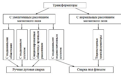
Rice. 1. Classification of welding transformers
For a typical transformer circuit, the main magnetic field loss on the path from the primary to the secondary winding occurs between the cores of the magnetic circuit.
The dissipation of the magnetic field is controlled by changing the geometry of the air gap between the primary and secondary windings (moving coils, moving shunts), by a coordinated change in the number of turns of the primary and secondary windings, by changing the magnetic permeability between cores of the magnetic circuit ( magnetized shunt).
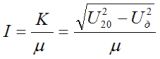
When considering a simplified diagram of a transformer with distributed windings, it is possible to obtain the dependence of the inductive resistance on the main parameters of the transformer
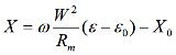
Rm is the resistance along the path of the stray magnetic flux, ε is the relative displacement of the coils, W is the number of turns of the coils.
Then the current in the secondary circuit:
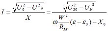
Infinitely variable range of modern welding transformers: 1: 3; 1: 4.
Many welding transformers have step control — switching both the primary and secondary windings to parallel or series connection.
I = K / W2
Modern welding transformers to reduce the weight and cost of the stage of high currents, the voltage of the open circuit is reduced.
Welded transformers with movable coils
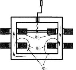
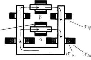
Rice. 2. The device of a welding transformer with movable windings: when the windings are fully offset, the welding current is maximum, when the windings are separated, it is minimum.
This scheme is also used in welding rectifiers of adjustable transformers.
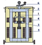
Rice. 3. The design of the transformer with movable windings: 1 — lead screw, 2 — magnetic circuit, 3 — leading nut, 4,5 — secondary and primary windings, 6 — handle.
Welding of mobile shunt transformers
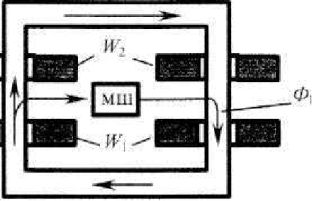
Rice. 4. The device of a welding transformer with a movable shunt
In this case, the regulation of the leakage flux of the magnetic field is done by changing the length and section of the elements of the magnetic path between the rods of the magnetic circuit. Because magnetic permeability iron is two orders of magnitude greater than air permeability; when the magnetic shunt moves, the magnetic resistance of the leakage current passing through the air changes. With a fully inserted shunt, the leakage current waveform and inductive resistance are determined by the air gaps between the magnetic circuit and the shunt.
Currently, welding transformers according to this scheme are produced for industrial and domestic purposes, and such a scheme is used when welding rectifiers of adjustable transformers.
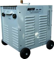
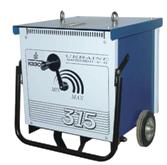
Welding transformer TDM500-S
Welding transformers with sectional winding
These are assembly and household transformers produced 60, 70, 80 years ago.
There are several stages of regulation of the number of turns of the primary and secondary winding.
Fixed shunt welding transformers
Rice. 4. The device of a welding transformer with a fixed magnetic shunt
A falling section is used for control, i.e. shunt core operation in saturation mode. Because the magnetic flux passing through the shunt is variable, the operating point is chosen so that it does not go outside the falling branch magnetic permeability.
As the saturation of the magnetic circuit increases, the magnetic permeability of the shunt decreases, accordingly, the leakage current, the inductive resistance of the transformer increases, and as a result, the welding current decreases.
Since the regulation is electrical, remote control of the power supply is possible. Another advantage of the circuit is the absence of moving parts, because electromagnetic control, this makes it possible to simplify and facilitate the design of power transformers. Electromagnetic forces are proportional to the square of the current, so at high currents there is a problem with supporting moving parts. Transformers of this type were produced in the 70s and 80s of the 20th century.
Thyristor welding transformers
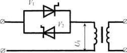
Rice. 5. Device thyristor welding transformer
Principle of voltage and current regulation thyristors based on the phase shift of the thyristor hole in the half-period of its direct polarity. At the same time, the average value of the rectified voltage and, accordingly, the current for a half cycle change.
To provide regulation of a single-phase network, you need two oppositely connected thyristors, and the regulation must be symmetrical.Thyristor transformers have a rigid external static characteristic that is controlled by the output voltage using thyristors.
Thyristors are convenient for voltage and current regulation in AC circuits because they close automatically when polarity is reversed.
In DC circuits, resonant circuits with inductance are usually used to close thyristors, which is difficult and expensive and limits the possibilities of regulation.
In thyristor transformer circuits, thyristors are installed in the primary winding circuit for two reasons:
1. Because the secondary currents of welding power sources are much higher than the maximum current of the thyristor (up to 800 A).
2. Higher efficiency, since the voltage drop losses in the open valves in the first loop are several times smaller than the operating voltage.
In addition, the inductance of the transformer in this case provides greater smoothing of the rectified current than in the case of installing thyristors in the secondary circuit.
All modern welding transformers are made with aluminum windings. For reliability, copper strips are cold welded at the ends.
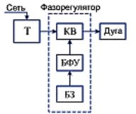
Rice. 6. Block diagram of thyristor transformer: T — three-phase step-down transformer, KV — switching valves (thyristors), BFU — phase control device, BZ — task block.
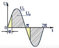
Rice. 7. Voltage diagram: φ- angle (phase) of turning on thyristors.
Since the 1980s, the majority of welding transformers have been made of cold-rolled transformer iron. This gives 1.5 times more induction and less weight of the magnetic circuit.