Classification and device of welding rectifiers
 A welding rectifier is a source of direct welding current. The welding rectifier contains power transformer, supply semiconductor valves and welding current control device.
Classification of welding rectifiers manufactured according to the second of the three main functions of the power source (combustion, regulation, transformation). All welding rectifiers, according to the method of adjusting the welding current, can be divided into transformer-controlled, thyristor and saturating chokes.
Transformer-regulated rectifiers have 3-phase transformers, unlike welding transformers, which are single-phase.
Step regulation is done by star-delta switching, which causes the current to change 3 times. (higher current with delta-delta than star-star.)
Unlike welding transformers, even the simplest rectifiers contain ballasts and protective equipment to protect the valves from overcurrent and cooling disturbances (fan relay or water pressure switch).
To do this, the power source must have a power contactor, it is manually controlled by the START and STOP buttons. For the rectifier VD-306: protection against electromagnetic current triggered when the permissible current is exceeded by 1.5 times.
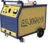
Rice. 1. Welding rectifier VD-306
The following elements can be distinguished in any welding rectifier: a step-down power transformer and a rectifier. The transformers used in welding rectifiers are slightly different from those described here — Classification and device of welding transformers.
The main difference is that welding rectifier transformers are three-phase. This not only ensures uniform loading of the phases of the power network, but also reduces ripples in the rectified current.
A common element of the welding rectifier is a choke... If it is located between the electrode holder and the rectifier block (in the section of the welding circuit where direct current flows), then it serves to limit the rate of increase of the short-circuit current, i.e. is. to reduce welding spatter.
If the choke is located between the power transformer and the rectifier block (in the section of the welding circuit where the alternating current flows), it serves to regulate the welding current or output voltage.
Rectifier blocks are assembled from power diodes. Unlike electrical current conductors, which conduct current equally well in both directions, diodes only pass current in one direction. It is impossible to control the amount of current using a diode.
In addition to diodes, welding rectifiers are used thyristors… Using a thyristor you can control the current. However, control options are limited. The thyristor cannot be turned off before the voltage on the main electrodes drops to zero. Therefore, thyristors are called "not fully controllable semiconductors". Fully controllable semiconductors are transistors (triodes), but their use in welding sources is limited.
Semiconductor elements must be protected from overheating. Therefore, diodes and thyristors are placed in radiators that are forced to cool by the air flow from the fan.
In welding chains thanks to EMF of self-induction sometimes voltage spikes (surges) occur that can cause the semiconductor to reverse breakdown. To prevent this, semiconductors bridge R — With circuit... When an increased voltage appears at the terminals of the semiconductor, the capacitor is charged and then discharged through the semiconductor in the forward direction.
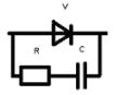
Rice. 2. Semiconductor protective circuit against inductive voltage
In welding rectifiers, semiconductor elements are assembled in the form of various circuits. It is divided into 1- and 3-phase correction.
Single-phase correction circuits They are used in control circuits where power consumption is low, therefore, with the help of smoothing capacitive filters, it is possible to obtain a voltage close to constant at the output.
Three-phase rectifier circuits
Welding rectifiers usually use three-phase rectifier circuitswhich provide significantly lower rectified current ripple compared to single-phase circuits.
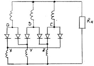
Three-phase Larionov rectification bridge circuit
In three-phase rectifiers, diode blocks are most often implemented in a bridge circuit. In this case, the rectified voltage ripple is 300 Hz.
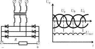
Rice. 3. Larionov's three-phase bridge rectifier circuit (a), phase and rectified voltage (b)
Circuit operation: The valves with the highest phase potential are connected to the anode group and vice versa to the cathode group. At all times, the valves are open, connected to the phases with the greatest positive and greatest negative potential. In addition, each valve of one group during one-third of the period operates in series with two valves of another group.
In welding equipment, this scheme is used in almost all rectifiers for manual arc welding with a rated current of up to 500A.
Ring three-phase rectifier circuit
For its implementation, the rectifier transformer must have two identical sets of secondary windings connected to a star and switched on with an offset of half the period of the mains frequency. In this case, the rectified voltage ripple is 300 Hz.
Rice. 4. Ring three-phase rectifier circuit
Circuit Operation: In this circuit, when the valve is switched on, one of the two coils in the rectifier circuit is also switched.In addition, each coil of one group for one-third of the period operates in series with two coils of another group.
The main disadvantage of this rectification circuit is that it requires a more complex and expensive transformer, which is designed taking into account the deviation of the DC component of the current.
Six-phase rectification circuit with equalizing reactor
For its implementation, the rectifier transformer must also have two identical groups of secondary windings connected in a star and switched on with an offset of half the period of the mains frequency. In addition, to ensure parallel operation of two phases at the same time on the load, an equalizing reactor is required - a symmetrical choke.
Six-phase rectifier circuit with surge reactor
Circuit Operation: For each star, the valves with the highest positive phase potential are turned on, similar to a three-phase neutral circuit. Without an equalizing reactor, six-phase rectification is obtained with the operation of each phase and a 1/6 period valve.
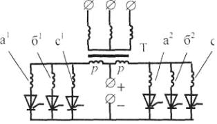
Rice. 5. Six-phase rectification circuit with equalizing reactor
Such a scheme is used in high-power rectifiers (1000 A and more), mainly for low-voltage power supply.
The main disadvantage of this rectification circuit is that it requires a more complex and expensive transformer, which is designed taking into account the deviation of the DC component of the current, as well as an additional choke.
Welding rectifiers with transformer regulation
The drooping characteristic of welding rectifiers is obtained in different ways. The simplest is that the welding rectifier is equipped with a drooping characteristic power transformer.The welding rectifier VD-306 is designed according to this principle.
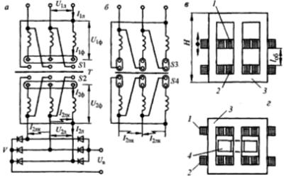
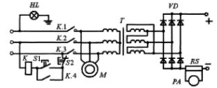
Rice. 6. Welding rectifier controlled by a transformer with increased dispersion: a, b — electrical circuits, c, d — transformer construction.
It includes a power transformer with movable windings or shunt, a rectifier and a starting protection. Rough current regulation is carried out by simultaneously switching the primary and secondary windings from the «star» (λ / λ) to the «delta» circuit (∆ / ∆). In the first case, a stage of small currents is set, and in the second - large ones. Within each stage, a smooth adjustment of the current is carried out by changing the distance between the primary and secondary windings.
The rectifier block is assembled on silicon diodes that are forced cooled by a fan. The rectifier switches on and off. magnetic starter.
The protective equipment does not allow the rectifier to turn on if the air flow is not supplied to the diodes, as well as if one of the diodes does not work or there is an interruption of the mains voltage to the box. The start-up protection equipment described is traditional for welding rectifiers.
Welding rectifiers of the considered type are easy to manufacture and operate. Their disadvantages are the lack of stabilization of the mode when the mains voltage changes and the impossibility of remote control.
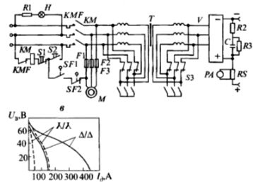
Rice. 7. Electrical schematic diagram of the welding rectifier VD-306
Rice. 8. Electrical schematic diagram of the welding rectifier VD-313
Welding rectifiers with thyristor control
Thyristor rectifiers, in addition to a transformer and valve block, contain a filter choke in the supply circuit and sensors and electronic blocks in the control system.
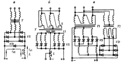
Rice. 9. Schemes of thyristor welding rectifiers: a — with a three-phase bridge, b — with a six-phase with equalizing choke, c — with a ring rectifier circuit
Welding rectifiers adjustable by saturation choke
Saturated chokes are also used to obtain drooping characteristics in welding rectifiers. An inductive reactance choke is placed between the power transformer and the rectifier block. The power transformer in the rectifier has a rigid external characteristic. The drooping characteristic of the rectifier is provided by the inductive resistance of the inductor.
Multistation welding rectifiers
Welding rectifiers with rigid external characteristics are used for multi-station welding - semi-automatic and manual. In the first case, they provide for the possibility of adjusting the output voltage, and in the second - not. Thus, the multi-station welding rectifier is the simplest in design.