Welding generators
 Welding generators are part of welding converters and welding units.
A welding converter contains a driving three-phase electric motor, a direct current welding generator and a welding current control device.
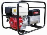
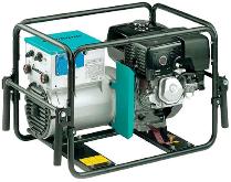
A welder contains an internal combustion drive engine, a DC welding electric generator and a welding current control device.
Welding generators They are divided by manifold and valve design and by the principle of operation on self-excited and independently excited generators.
Collector welded generators with independent excitation used in welding converters, whose production in our country was discontinued in the 90s of the 20th century, but are still in operation in some organizations.
Other types of generators are currently part of welding machines.
Collector generators for welding
Collector generators are DC machines containing a stator with magnetic poles and windings, and a rotor with windings whose ends lead to the collector plates.
When the rotor rotates, the turns of its winding cross the lines of force of the magnetic field and in them EMF induced.
The graphite brushes make movable contact with the collector plates. The brushes of the machine are located on the electrical (geometric) neutral of the collector, where the EMF in the turns changes its direction. If you move the brushes from neutral, the voltage of the generator will decrease and the switching of the coils will occur under voltage, which in welding generators under load will cause the collector to melt very quickly by an electric arc.
The EMF on the brushes of the welding generator is proportional magnetic fluxcreated by the magnetic poles E2 = cF, where F is the magnetic flux; c is the constant of the generator, determined by its design and depending on the number of pairs of poles, the number of turns in the armature winding, the speed of rotation of the armature.
Output voltage of the generator under load U2 = E2 — JсвRr, where U2 — output voltage of the terminals of the generator under load; Jw — welding current; Rg is the total resistance of the armature section in the generator and the brush contacts.
Therefore, the external static characteristic of such a generator falls slightly. To obtain a steeply falling external static characteristic in collector generators, the principle of internal demagnetization of the machine is applied, which is provided by the stator demagnetization coil. If it is necessary to obtain a rigid external static characteristic, a magnetizing stator winding is used.
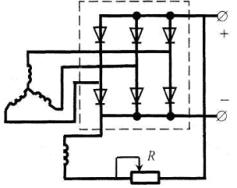
Independently excited welding generator with degaussing coil
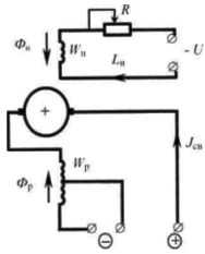
Rice. 1 Schematic of a welding generator with independent excitation and a demagnetizing coil
A distinctive feature of such a generator is that two magnetic coils are located on the magnetic poles. One (magnetizing) is powered by an external power source (independently excited) while the other (demagnetizing) is used for the welding current.
The degaussing coil, acting as a resistance connected in series with the arc, provides a drooping characteristic of the generator, and when split, adjusts the current in steps.
The inclusion of all turns of the degaussing coil in operation gives a low current stage, and the inclusion of part of the turns gives a high current stage.
 Smooth adjustment of the welding current is carried out by changing the open circuit voltage, for which the rheostat R is used in the coil magnetizing circuit. An increase in the resistance R leads to a decrease in the magnetizing current, a decrease in the magnetizing flux Fn, the open circuit voltage of the generator, and finally to a decrease in the welding current.
The generator provides a falling external static characteristic only when rotating in one direction, indicated by an arrow on the housing. With welding converters, it is necessary to check the correct direction of rotation of the electric motor before welding at idle speed.
Self-starting welding generator with demagnetizing coil
The main difference between this type of generators is that the magnetic field coil is powered not by an external source, but by the generator itself. Therefore, they are called self-excited generators.
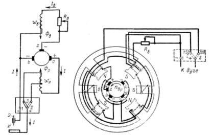
Rice. 2. Schematic diagram and arrangement of the magnetic system of a four-pole self-excited generator
In collector welding generators, in addition to the main poles and coils, there are two additional poles, on which an additional series coil is placed along the turn. This is necessary to compensate for the magnetic flux from the armature reaction and to maintain the position of electrical neutrality of the machine when the load changes.
For normal operation of a self-excited generator, it is necessary that the voltage applied to the magnetizing coil does not change during the welding process, i.e. does not depend on the welding mode. For this purpose, a third additional brush is installed in the generator, which is located between the two main brushes.
The voltage supplying the magnetizing coil turns out to be independent of the welding current. The falling characteristic of the generator is provided due to the demagnetizing effect of the demagnetizing coil, which occurs under the second half of the poles.
 A feature of self-excited welding generators is that they can be started only when the armature is rotated in one direction, indicated by the arrow on the stator end cover. This is due to the fact that the initial excitation of the generator at its start is due to the residual magnetization of the poles.
When the armature is rotated in the opposite direction, a reverse current will flow in the excitation coil, which with its increasing magnetic field at a certain point in time compensates for the residual magnetization of the poles, i.e. the total magnetic flux below the poles will be zero. In this case, in order to excite the generator, it is necessary to temporarily connect the magnetizing coil to an independent direct current source.
Valve welding generators
Welding generators of this type appeared in the mid-70s of the 20th century after the development of the production of power silicon valves. In these generators, the function of correcting the current instead of the collector is performed by a semiconductor rectifier, to which the alternating voltage of the generator is supplied.
In welding units, generators of three types of alternator construction are used: inductor, synchronous and asynchronous. In Russia, welding devices are produced with self-exciting, independent excitation and mixed induction excitation generators.
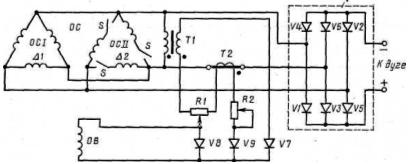
Rice. 3. Schematic of a valve generator with self-excitation
In an inductor generator, the stationary field coil is supplied with direct current, but the magnetic flux created by it is variable in nature. It is maximum when the rotor and stator teeth coincide, when the magnetic resistance in the flux path is minimum, and is minimum when the rotor and stator cavities coincide. Therefore, the EMF induced by this flux is also variable.
Three working windings with an offset of 120 ° are located on the stator, so a three-phase alternating voltage is generated at the output of the generator. The falling characteristic of the generator is obtained due to the large inductive resistance of the generator itself. The rheostat in the excitation circuit is used to smoothly adjust the welding current.
The absence of sliding contacts (between the brushes and the collector) makes this generator more reliable in operation. In addition, it has higher efficiency, less weight and dimensions than the collector generator.
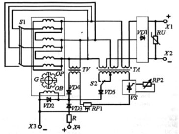
Rice. 4. Schematic diagram of a valve-type welding generator of the GD-312 type with self-excitation
To ensure no-load operation, the excitation coil is supplied by a voltage transformer, and to supply it in short-circuit mode by a current transformer. In the load mode - welding - a mixed control signal proportional to the part of the output voltage and proportional to the current is applied to the excitation coil. Valve generators are manufactured under the GD-312 brand and are used for manual metal welding as part of ADB blocks.
Rice. 5. Schematic diagram of the welding generator GD-4006
In Russia, several designs of multi-position units with the number of positions from 2x to 4x are produced. There are universal units on the market for several methods of welding or welding and plasma cutting. In particular, the ADDU-4001PR module.
The formation of an artificial VSH unit ADDU-4001PR is provided by a thyristor power supply unit with microprocessor control. Wider technological possibilities are provided by the use of inverter power units in units, such as in the Vantage 500 unit.