Schemes for transmission and distribution of electricity in the enterprise
 Schemes for powering workshops in the enterprise are very diverse, and their construction is due to many factors: the category of electrical receivers, the territory, the historical development of the enterprise and many others. Therefore, we will dwell only on the basic principles of building schemes.
One of the main principles for building a power supply scheme is the use of deep input, which means the maximum possible approximation of high voltage sources or substations to consumers with a minimum number of intermediate stages of transformation and devices.
In medium-sized enterprises, deep input lines with a voltage of 35-110 kV are introduced into the territory directly from the power system. In large utilities, deep bushings are diverted from the main step-down substation (GPP) or distribution substations that receive power from the power system.
In small enterprises, it is enough to have one substation to receive electricity.If the supply voltage matches the voltage of the factory distribution network, then electricity is received directly at the distribution point without transformation.
The distribution of electricity in the enterprise can be carried out according to radial, trunk or combined schemes. The choice of a particular scheme is influenced by technical and economic factors.
When placing loads in different directions from the power center, it is recommended to use radial power transmission and distribution... Depending on the capacity of the enterprise, radial circuits can have one or two stages of power distribution. Two-stage radial chains with intermediate RPs are used in high-power enterprises. Intermediate RPs make it possible to free the GPR tires from a large number of small output lines.
Typical power supply schemes for industrial plants
In fig. 1 shows a typical radial feed made in two stages. All switchgear is installed on RP1-RP3, and the transformer substations fed by them are provided with a fuse-disconnector connection. RP1 and RP2 are fed by two lines and RP3 by one line from the GPP (first stage) buses. In the second stage, the electricity is distributed between the TP of two transformers and one transformer.
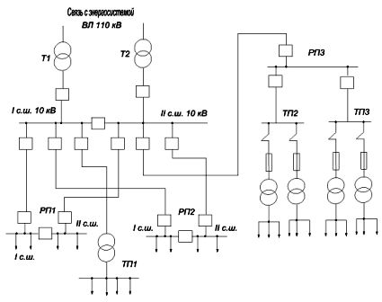
Rice. 1. Radial feed diagram
Mains power transmission and distribution schemes are used when loads are located in one direction from the power source. Electricity is supplied to the substations by branches from the line (overhead or cable), successively entering several substations.The number of transformers connected to one line depends on the power of the transformers and the continuous supply required. Trunk circuits can be performed with one, two or more trunks.
In fig. 2 transmission scheme with a double line when feeding a two-transformer TP... These schemes, despite their high cost, are very reliable and can be used for receivers of any category.
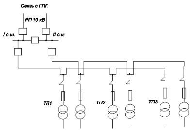
Rice. 2. Trunk power supply diagram
The reliability of the main circuit is due to the fact that the transformers of the transformer substation are fed by different networks, each of which is designed to cover the main loads of all transformer substations. In this case, the transformers are also designed for mutual shorting. The busbar sections of the RP or TE transformers of the workshop operate separately during normal operation and if one of the lines is damaged, they switch to the line that remains in service.
Trunk lines for transmission and distribution of electricity allow to reduce costs compared to radial costs by reducing the length of supply lines, reducing switching equipment. However, compared to radials, they are less reliable, since the failure of the line leads to the disconnection of all consumers fed by it.