Electrical measurements after installation and during operation of elevators
 Before commissioning, after repair and periodically under operating conditions, the condition of insulation and grounding of electrical networks and equipment is checked on the elevators. The volume, time and norms of electrical measurements are determined by the «Rules for the installation of electrical installations» (PUE), «Rules for the technical operation of consumer electrical installations» (PTEEP), «Safety rules for the operation of consumer electrical installations» Installations « (PTB) and manufacturing instructions.
In the production of acceptance tests of electrical equipment, it is necessary to be guided by PUE. Preventive and other operational tests are carried out in accordance with the requirements of PTEEP and PTB and production instructions.
Electrical work on elevators consists of the following operations: checking the condition of the insulation in all sections of the elevator wiring diagram, checking the impedance of the "phase - zero" loop of the elevators, measuring the resistance of the grounding device, checking the presence of a circuit between the grounding electrodes, the grounded neutral wire and the grounded elements, checking the protective grounding of the network to determine the reliability and correctness of its design.
Measurements of insulation resistance and testing of grounding devices prevent interruptions in the continuous supply of electricity to elevators, deviations from the specified mode of operation and ensure safe working conditions.
Protocols are drawn up for each type of electrical work. The measurement of the insulation resistance of the electrical circuits, the inspection of the protective earthing devices of the elevators must be carried out by at least two persons who have a qualification group for safety measures of at least III, and the insulation tests with increased voltage are carried out by teams of at least two people, of whom the senior group (work producer) must have a qualification group of at least IV, and the rest at least III.
Measurement of the insulation resistance of electrical equipment and elevator networks
The insulation is constantly destroyed under the influence of the environment, mechanical loads, moisture, dust, temperature and other factors.To prevent the destruction of the insulation and, accordingly, the occurrence of the danger of electric shock to people, to prevent the tripping or damage of the installation — the main purpose of measuring the insulation resistance of electrical circuits and elevator equipment.
The insulation is tested on newly built and reconstructed elevators, during major repairs and at least once a year under operational conditions. Insulation of windings of electric motors, electrical equipment and all sections of the elevator circuit is tested.
Two methods are used to test the insulation of elevator electrical equipment: insulation resistance measurement and increased voltage insulation testing. The first method is used for all checks, the second — in cases when the insulation resistance of the tested section is less than the value provided by the standards.
Insulation resistance is measured with a portable magnetoelectric megohmmeter M-1101 with an operating voltage of 500 and 1000 V. It is convenient to test insulation with increased voltage of elevators with a megohmmeter MS-05 for 2500 V.
Any electrical resistance, including insulation resistance, is measured in ohms (megohms). For electric motors in a cold state, the insulation resistance of the windings must be at least 1 MΩ at temperatures above + 60 ° C — at least 0.5 MΩ . The insulation resistance of electrical equipment and wiring should be at least 0.5 MΩ, and the insulation resistance of the control circuit should be at least 1 MΩ. Insulation resistance is one of the main indicators of the technical condition of the elevator and its safety.Periodic inspection of the insulation, monitoring of its operation are mandatory. Without checking the condition of the insulation, the elevator cannot be put into operation.
A technique for measuring the insulation resistance of elevators
Before starting the measurement of the insulation resistance of the electrical equipment of the elevator, the installation at the entrance is turned off and placards are placed, in accordance with the requirements of the safety rules, the absence of voltage and discharge of capacitive currents to the ground are checked. They also check the megohmmeter and the wires to it.
The conductors must be flexible, with a cross-section of 1.5 — 2 mm2 with an insulation resistance of at least 100 megohms. To check the megohmmeter, one wire is fixed in the "earth" clamp, the second - in the "line" clamp, their ends are short-circuited and the handle of the device is turned. In this case, the arrow should go to zero. With the ends of the wires open, the needle on the megger should read "Infinity".
When working with a megohmmeter, the device is mounted horizontally. When measuring, the speed of the megger handle is approximately 120 rpm. To establish the exact value of the insulation resistance, the readings of the device are taken 1 min after applying the voltage, when the needle of the device takes a stable position.
The insulation of the stator windings of electric motors, brake magnetic coils, power supply and lighting circuits is checked between phases and with respect to "ground" (body). The insulation of the control circuits and the rotor of the electric motor is checked against ground.
On the transformer, measure the insulation resistance of each winding to ground and between the primary and secondary windings. When checking the insulation of the windings of a low-voltage transformer, the primary winding is measured against "earth" and between the primary and secondary windings. In the latter case, it is necessary to disconnect the low voltage winding from the ground.
When measuring insulation resistance in power circuits, electrical receivers, as well as devices, tools, etc., must be turned off. When measuring the insulation resistance in lighting circuits, the lamps must be developed, and the contacts, switches and group screens must be connected. The insulation resistance of the control circuits is measured with all connected devices.
In all cases, insulation resistance is measured with fuses removed. Individual inspection is carried out regardless of the number and length of wires in each section.
Example list of areas for testing the insulation resistance of an elevator
1. Section of the input device feeding the elevator to the machine (fuses).
2. Section from circuit breaker (fuses) to limit switch.
3. Section from limit switch to contactor panel.
4. Section from contactor panel to line contactor.
5. Section from the linear contactor to the electric motor.
6. Lead to electromagnetic brake.
7. Selenium rectifier.
8. Motor windings.
9. Electromagnetic brake coil.
10. Transformer windings of the attachment.
11. The section from fuses to the cabin magnetic circuit.
12. Winding the magnetic branch.
13. Fuse section to transformer 380/220 V.
14.Transformer windings 380/220 V.
15. Section from fuses to transformer 380/24 V, 220/24/36 V.
16. Transformer winding 380/24 V, 220/24/36 V.
17. Section from the contactor panel to the 380/220 V transformer feeding the electric motor of the door mechanism (at a supply voltage of 380 V).
eighteen. The windings of the 380/220 V transformer supplying the electric motor of the door mechanism.
19. From a 380/220 V transformer to an automatic machine that includes the electric motor of the door mechanism.
20. From the machine to the electric motor of the door mechanism.
21. Windings of the stator of the electric motor of the door mechanism.
22. Signal and lighting circuits (measurements relative to ground).
23. Contact line (control circuit).
24. Motor rotor winding.
25. Section from the rotor of the electric motor to the starting rheostat.
26. Starting rheostat.
27. Section between control, lighting and signaling circuits.
Measurements with a megohmmeter should be carried out by two workers (one turns the handle of the megger and reads the readings on the scale, and the other reliably connects the wires with clamps to the circuit under test). At mains voltage from 60 to 380 V, the insulation resistance is measured with a 1000 V megometer, at mains voltage up to 60 V — with a 500 V megometer.
When measuring the insulation resistance to earth, the wire from the earth clamp should be connected to the earth loop (neutral wire) or the housing of the equipment under test, and the wire from the terminal line to its phase or winding.When measuring the insulation resistance between the phases (windings), both wires from the device are connected to the current-carrying wires of the tested phases (windings).
Megohmmeters of the M-1101 type have a third clamp ("Screen"), which is used to exclude the influence of surface leakage currents on the result of the insulation resistance measurement. It is used in cases where the surface of the isolated area to be measured is heavily wetted. In this case, the wire from the "Screen" bracket is connected to the cable sheath, to the motor housing, etc.
The connection diagrams of a megohmmeter when checking the insulation resistance to "earth", between phases with the exclusion of surface leakages, are shown in fig. 1.
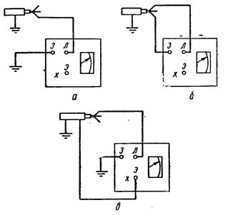
Rice. 1. Schemes for measuring the insulation resistance with a megohmmeter: a — to the ground, b — between the phases, c — to the ground with the exclusion of surface leaks
When testing insulation with increased voltage, it should be applied for 1 min. It is considered that the section of the circuit or winding of the electrical receiver has passed the dielectric strength test and may be allowed for further work if during test no failure occurred.
The connection diagram of the MS-0.5 megometer during the production of insulation tests with increased voltage is shown in Fig. 2.
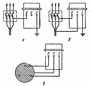
Rice. 2. Schemes for testing insulation with increased voltage with a megohmmeter MS -0.5: a — to the ground, b — to the ground, excluding surface leaks, c — between the phases.
A general conclusion on the condition of the insulation of the electrical equipment and elevator circuits is given based on the measurement data for each section and external examination of the entire installation.
Elevator ground testing
All metal parts of the elevator that may be live due to insulation damage must be reliably grounded. Under operating conditions, at least once a year, measure the resistance of the grounding device and check the presence of a circuit between the grounding conductors (grounded neutral wire) and the grounded elements of the equipment (checking the transient resistance in the contacts) and at least once every 5 years the impedance of the loop «phase-zero».
Inspection of grounding devices is necessary to exclude the possibility of electric shock to people. Protective earthing in installations with an isolated neutral reduces the touch voltage that occurs on electrical equipment boxes in the event of insulation failure to safely below 40 V.
The resistance of the transient contacts is measured with an ohmmeter M-372 with a scale of 0-50 ohms. The resistance of the grounding device of the elevator is most convenient to produce with a grounding meter type M-416. The resistance of the protective grounding should not exceed 4 ohms.
A grounding device is a combination of a grounding electrode and grounding conductors. Earthing switches are metal conductors or a group of conductors that are in direct contact with the ground. Grounding wires are metal wires that connect the grounded parts of the electrical installation to the grounding electrode.A transient contact with a resistance of not more than 0.05 ohms is considered satisfactory.
Along with checking with tools is necessary visual inspection ground wiring to determine the correctness of its design. Bare copper earthing conductors with open laying must have a cross section of at least 4 mm2, insulated copper conductors used for grounding — at least 1.5 mm2.
Aluminum grounding conductors must have a cross-section of b and 2.5 mm2, respectively. Steel steel wires with a round profile must have a diameter of at least 5 mm, and on a rectangular profile - a twist of at least 24 mm2 with a thickness of at least 3 mm.
The ground wire of portable (mobile) electrical receivers is a separate core in a common sheath with phase wires of the same cross-section, but not less than 1.5 mm2. The wire should be soft flexible.
Grounding conductors are connected to each other by welding, and to the equipment to be grounded by welding or bolting.
It is recommended to test grounding devices in sequence during periods of maximum drying and freezing of the soil. Measurements are not allowed in wet weather.