Gas protection of transformers
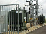 Gas protection for transformers is the most sensitive and universal protection against internal damage. Installed on oil cooled transformers with oil conservator.
This type of protection is based on the fact that any damage in the transformer, including increased heating of the oil, leads to chemical decomposition of the transformer oil, as well as organic materials from the winding insulation, as a result of which gas is released inside the transformer. This gas acts on special gas protection devices that give a warning signal or switch off the transformer.
 Gas protection reacts to faults such as short-circuit interruption in the transformer windings, to which differential and overcurrent protection do not react; because in such cases the magnitude of the fault current is insufficient for the protection to operate.
The nature of the fault in the transformer and the extent of the fault affect the rate of gas formation. If the fault develops slowly, corresponding to slow gassing, then the protection gives a warning signal but does not disconnect the transformer.
The intense and even violent formation of gas, which indicates a short circuit, creates a signal in the gas protection system of such magnitude that, in addition to the warning, it causes the tripping of the defective transformer. The gas protection of the transformers triggers a warning signal even when the oil level in the tank drops.
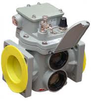
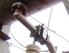
Gas protection of transformers carried out by special gas relays, mounted in a metal housing, built into the oil pipeline between the tank and the expander.
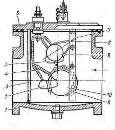
Rice. 1. Float-type gas relay: 1 — body, 2.5 — contacts, 3 — rod, 4 — terminal insulation, 6 — cover, 7 — frame, 8 — axis, 9 — upper float, 10 — lower float.
The relay is usually filled with oil. The relay housing has a mirror glass with a scale showing the amount of accumulated gas and the relay. At the top of the relay there is a gas release valve and clamps for connecting wires to the contacts located inside the relay.
The design and installation of the most common gas relay of the PG-22 type is shown in fig. 1. In gas relays of this type, two floats are mounted on hinges inside the housing, which are hollow metal cylinders, and on them there are mercury contacts connected by flexible wires to the terminal clamps of the cover relay. The upper float is a protected signaling element.
 In normal condition, when the relay is completely filled with oil, the float floats and its contact opens. In slow gassing, the gases rising to the expander gradually fill the relay and displace the oil. As the oil level decreases, the descending float turns on its axis while the mercury contacts close and a warning signal is sent.
With further slow gas formation, the relay cannot act on shutdown because it is filled with gas only to the upper edge of the hole, after which the gases will pass into the expander.
The lower float, located opposite the opening of the oil pipeline, is a shut-off element. If gas formation occurs violently, then a strong flow of gases from the transformer to the expander occurs through the gas relay, while the lower float turns over, closes the mercury contacts, which activates the device , which turns off the transformer.
Since during a short circuit, a violent gas formation immediately occurs in the transformer tank, the transformer switches off quickly after 0.1-0.3 s. A little later, after the transformer is turned off, the alarm is triggered.
For transformers with a capacity of 6.3 thousand kVA and more, the installation of gas protection is mandatory. For transformers with a capacity of 1000 to 4000 kVA, it is mandatory only in the absence of differential or overcurrent current protection with a delay of 0.5-1 s. For transformers with a capacity of 400 kVA and above installed inside the workshop, gas protection is mandatory.