Measurement of the insulation resistance of an installation at operating voltage
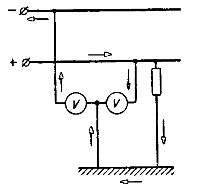
 If the network (installation) is under operating voltage, then its insulation resistance can be determined using a voltmeter (Fig. 1).
To measure insulation, we determine:
1) network operating voltage U;
2) voltage between wire A and ground UA (voltmeter reading in position A of the switch);
3) voltage between wire B and ground UB (voltmeter reading in position of switch B).
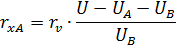
By connecting the voltmeter to wire A and designating rv the resistance of the voltmeter, rxA and rxB the insulation resistance of wires A and B to ground, we can write the expression for the current flowing through the insulation of wire B;
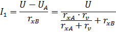
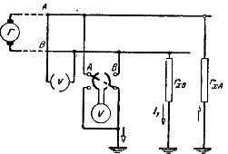
Figure 1. Scheme for measuring the insulation resistance of a two-wire network with a voltmeter.
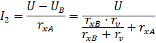
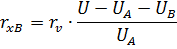
By connecting a voltmeter to wire B, we can write an expression for the current flowing through the insulation of wire A.
Solving together the two resulting equations for rxA and rxB, we find the insulation resistance of conductor A to ground:
and the insulation resistance of conductor B with respect to ground
Noting the readings of the voltmeters when they are turned on and substituting these readings into the above formulas, we find the values of the insulation resistance of each of the wires relative to ground.
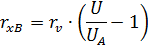
If the insulation resistance of wire A to ground is large compared to the resistance of the voltmeter, then when the switch is in position A, the voltmeter will be connected in series with the insulation resistance rxB, the value of which in this case can be determined by the formula:
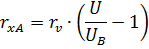
Similarly, if the resistance rxB is large compared to the resistance of the voltmeter, then in position B of the switch, the voltmeter will be connected in series with the insulation resistance rxA, whose value is
From the last expressions it can be seen that the readings of the voltmeter connected between one wire and the ground, at a constant voltage of the network U, depend only on the insulation resistance of the second wire. Therefore, the voltmeter can be graduated in ohms, and from its reading you can directly estimate the value of the insulation resistance of the network ... These ohm-graded voltmeters are also called ohmmeters.
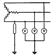
To monitor the condition of the insulation, instead of one voltmeter with a switch, you can use two voltmeters, including them according to the scheme shown in fig. 2. In this case, when the insulation is normal, each of the voltmeters will show a voltage equal to half the mains voltage.
Rice. 2.Scheme for monitoring the condition of the insulation of a two-wire network.
If the insulation resistance of one of the wires decreases, then the voltage on the voltmeter connected to this wire will drop, and on the second voltmeter will increase, since the equivalent resistance between the terminals of the first voltmeter decreases and the voltage in the network is distributed in proportion to the resistances.
In three-phase current networks, the condition of the insulation is also monitored using voltmeters connected between the conductors and the ground (Fig. 3).
Rice. 3. Scheme for monitoring the condition of the insulation of a three-phase network.
If the insulation of all the wires of the three-phase circuit is the same, then each of the voltmeters indicates the phase voltage. If the insulation resistance of one of the wires, for example the first one, begins to decrease, then the reading of the voltmeter connected to this wire will also decrease, since the potential difference between this wire and the ground will decrease. Simultaneously, the readings of the other two voltmeters will increase.
If the insulation resistance of the first wire drops to zero, then the potential difference between this wire and the ground will also be zero, and the first voltmeter will give a zero reading. At the same time, the potential difference between the second wire and the ground, as well as between the third wire and the ground , will increase to a line voltage that will be noted by the second and third voltmeters.
To monitor the condition of insulation in high-voltage three-phase current circuits with an ungrounded neutral, either three electrostatic voltmeters connected directly between the conductors and the ground are used (Fig.3), or three star-connected voltage transformers (Fig. 4), or five-level voltage transformers (Fig. 5).
Normally, three-level voltage transformers are not suitable for monitoring the insulation condition. In fact, when one of the phases of the installation is grounded, the primary winding of that phase of the voltage transformer will be short-circuited (Fig. 4), while the other two windings will be live on the line. As a result, the magnetic fluxes in the cores of these two phases will increase significantly and will be closed through the core of the shorted phase and through the transformer case. This magnetic flux will induce a significant current in the short-circuited winding, which can cause overheating and damage to the transformer.
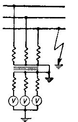
Figure 4 Scheme for monitoring the insulation condition of a three-phase high-voltage network
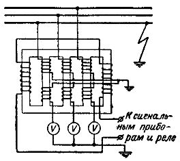
Fig. 5 Schematic of the device and the inclusion of a five-pole voltage transformer
In a five-bar transformer, when one of the installation phases is shorted to ground, the magnetic fluxes of the other two transformer phases will be closed through the additional transformer bars without causing the transformer to overheat.
Additional bars usually have windings to which relays and signaling devices are connected, which come into action when one of the installation phases is closed to earth, since the magnetic fluxes that appear in this case in additional bars induce e. etc. with