Setting up DC motors
 The regulation of direct current electric motors is carried out in the following scope: external examination, measurement of the resistances of the windings to direct current, measurement of the insulation resistances of the windings to the housing and between them, testing of interturn insulation of the armature winding, trial run.
External inspection of a DC motor, as well as inspection of an induction motor, begins with a shield. The following data must be indicated on the nameplate of the DC motor:
- the manufacturer's name or trade mark,
- car type,
- serial number of the machine,
- nominal data (power, voltage, current, speed),
- way to excite the machine,
- year of issue,
- weight and GOST of the machine.
Winding terminals permanent engine must be reliably isolated from each other and from the body, the distance between them and the body must be at least 12-15 mm. Special attention during the external examination is paid to collector and the mechanism of the brushes (brushes, traverses and brush holders), since their condition significantly affects the commutation of the machine and, therefore, the stability of its operation.
When inspecting the collector, they are convinced that there are no traces of milling cutters, holes, spots of varnish and paint on the working surface, as well as traces of carbon deposits from unsatisfactory operation of the brush mechanism. The insulation between the collector plates should be selected to a depth of 1–2 mm, the edges of the plates should be chamfered with a width of 0.5–1 mm (depending on the engine power). The gaps between the plates must be completely clean — they must not contain metal shavings or wood shavings, dust from graphite brushes, oil, varnish, etc.
The operation of a DC motor, and especially its brush mechanism, is affected by collector leakage and its vibrations. The higher the peripheral speed of the collector, the lower the allowable leakage. For high-speed motors, the maximum allowable leakage value should not exceed 0.02-0.025 mm. The magnitude of the vibration amplitude is measured with a dial indicator.
During the measurement, the tip of the indicator is pressed against the surface in the direction in which the vibration will be measured. Since the surface of the collector is interrupted (collector plates and recesses alternate), a well-sharpened brush is used, on which the tip of the indicator should rest. The indicator housing must be secured to a vibration-free base.
When measuring, the pointer of the indicator oscillates with the frequency of the measured vibration within a certain angle, the value of which is estimated on the scale of the indicator in hundredths of a millimeter. However, this device can measure vibrations at speeds up to 750 rpm.For engines with a rotation speed of more than 750 rpm, it is necessary to use special devices - vibrometers or vibrographs, which can measure or record the vibrations of certain components of the machine.
Leakage is also measured with an indicator. Manifold leakage is measured in both cold and hot engine conditions. When measuring, pay attention to the behavior of the indicator arrow. The smooth movement of the arrow indicates sufficient cylindricity of the surface, and the twitching of the arrow indicates local violations of the cylindricity of the surface, which is especially dangerous for the brush mechanism of the motor. The measurement of shocks is conditional, since work experience shows that there are motors, at which shock values are large at low rotational speeds and at nominal speed operate satisfactorily. Therefore, the final conclusion about the quality of the work of the collector can be given only after checking the operation of the engine under load.
When checking the mechanical part of a DC motor, you should pay attention to the condition of the rations and connections of the windings, bearing assemblies, the evenness of the gap (with the motor disassembled). The difference measured at diametrically opposite points between the armature and the main poles of the motor shall not differ from the average value by more than 10% for gaps less than 3 mm and not more than 5% for gaps greater than 3 mm
After checking the shocks and vibrations, they begin to adjust the brush mechanism of the motor. The brushes in the clips should move freely but should not wobble.The normal gap between the brush and the holder in the direction of rotation should not exceed 0.1-0.4 mm, in the longitudinal direction 0.2-0.5 mm.
The normal specific pressure of the brushes on the collector, depending on the grade of the brush material, should be at least 150-180 g / cm2 for graphite brushes, 220-250 g / cm2 for copper-graphite. To avoid uneven current distribution, the pressure of the individual brushes should not differ from the average by more than 10%. The specific pressure is determined as follows. A sheet of thin paper is placed between the collector and the brush, a dynamometer is attached to the brush, and then, pulling the brush with a dynamometer, they find a position where it will be possible to freely pull a sheet of paper. The dyno reading at this point corresponds to the brush pressure on the manifold. Specific pressure is determined by dividing the dynamometer reading by the brush base area.
The correct installation of the brushes is one of the most important factors for the correct operation of the machine. The brush holders are installed in such a way that the brushes are strictly parallel to the collector plates and the distances between their edges are equal to the separation of the poles of the machine with an error of no more than 2%.
In motors with several sleepers, the brush holders are placed in such a way that the brushes cover as much of the collector length as possible (the so-called stacked arrangement). This will make it possible to participate in commutation along the entire length of the collector, which contributes to its more uniform wear.However, with such an arrangement of the brushes, it is necessary to ensure that the brushes do not protrude during operation (taking into account the stroke of the shaft) beyond the edge of the collector. Before starting the engine, the brushes are carefully rubbed against the collector (Fig. 1) with medium-grit glass (but not carborundum) paper. Carborundum paper grains can penetrate the brush body and then during operation scratch the collector, thereby worsening the switching conditions of the machine.
Before proceeding to check the correctness of the inclusion of the windings, study the marking of the terminals of the machine of a certain type. In DC motors, the windings are designated according to GOST 183-66 with the first capital letters of their name, followed by the number 1 for the beginning of the winding and 2 for its end. If there are other windings with the same name in the motor, their beginnings and ends are marked with the numbers 3-4, 5-6, etc. The terminal markings may correspond to the excitation circuits and motor rotation directions shown in fig. 2.
The correctness of the inclusion of the pole windings is checked to clarify the alternation of their polarity. The polarity alternation of auxiliary and primary poles for each machine must be strictly defined for a given direction of rotation of the machine. When moving from pole to pole in the direction of rotation of the machine operating in motor mode, after each main pole there is an additional pole of the same polarity, for example N — n, S — s. The polarity of the poles can be determined in several ways: by visual inspection, using a magnetic needle and using a special coil.
The first method is used in cases where the winding direction of the coils can be traced visually.
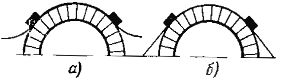
Rice. 1. Rubbing the brushes to the collector:. a — wrong; bright
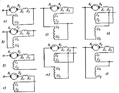
Rice. 2. Designations of the winding terminals of DC motors for different excitation schemes and directions of rotation
Knowing the direction of winding and using the "gimbal" rule, determine the polarity of the poles. This method is convenient for windings from a series field winding, the winding direction of which is very easy to determine due to the significant cross-section of the turns.
The second method is mainly used for coils with parallel excitation windings. The essence of this method is as follows. A current is applied to the winding of the motor, a magnetic needle is suspended on a thread, the polarity of the ends of which is marked, and is applied alternately to each pole. Depending on the polarity of the pole, the arrow will face it with the end of the opposite polarity.
When using this method, it should be remembered that the arrow has the ability to re-magic, therefore the experiment should be carried out as quickly as possible. The magnetic needle method is rarely used to determine the polarity of a series coil because a significant current must pass through the coil to produce a strong enough field.
The third method of determining the polarity of the coils is applicable to any coil, it is called the test coil method. The coil can be of any shape — toroidal, rectangular, cylindrical. The coil is wound with as many turns as possible of thin insulated copper wire on a frame of cardboard, celluloid, etc. Millivoltmeter.
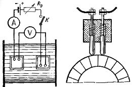
The connection of the coils is considered correct if under every two adjacent poles the arrows of the device deviate in different directions, provided that the test coil faces the poles on the same side. Checking the correct connection of the winding of the additional poles relative to the armature winding is carried out according to the scheme shown in fig. 4.
When switch K is closed, the millivoltmeter needle will deflect. When correctly switched on, the magnetizing force of the auxiliary pole winding is directed opposite to the magnetizing force of the armature winding, therefore the armature winding and the auxiliary pole winding must be turned on oppositely, that is, the minus (or plus) of the armature must be connected to the minus (or plus) of the winding of the additional poles.
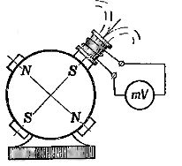
Rice. 3. Determining the polarity of the poles of DC motors using a test coil
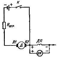
Rice. 4. Scheme for checking the correctness of the inclusion of the winding of the additional poles relative to the armature winding
To check the mutual connection of the winding of the additional poles and the compensation winding, you can use the scheme shown in fig. 5, for small engines.
In normal operation of a DC motor, the magnetic flux created by the compensating coil must match in direction with the magnetic flux of the complementary pole coil. After determining the polarity of the windings, the compensation winding and the winding of the additional poles must be connected together, that is, the minus of one winding must be connected to the plus of the other.
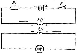
Rice. 5.Scheme for checking the correctness of the inclusion of the winding of additional poles to the compensation winding
Before determining the polarity of the brushes and making the necessary measurements of the coil resistances, set the brushes to neutral. The neutral of an electric motor means such a mutual arrangement of the windings of the main poles and the armature when the transformation coefficient between them is zero. To set the brushes to neutral, a chain is assembled (Fig. 6).
The excitation coil is connected to a power source (battery) through a switch, and a sensitive millivoltmeter is connected to the armature brushes. When a current is supplied to the excitation coil with a jerk, the needle of the millivoltmeter is deflected in one direction or another. When the brushes are positioned strictly in the neutral position, the needle of the device will not deviate.
The accuracy of conventional instruments is low — 0.5% at best. Therefore, the brushes are set to a position corresponding to the minimum reading of the device, and this is considered to be neutral. The difficulty in adjusting the neutral brushes is that the position of the neutral depends on the position of the collector plates.
It often happens that the neutral found for one armature position is displaced when rotated. The neutral position is therefore defined for two different shaft positions. If the position of the neutral turns out to be different for the different positions of the armature, then the brushes should be placed in an intermediate position between the two marks. The accuracy of setting the brushes to neutral depends on the degree of adhesion of the surface of the brush to the collector.Therefore, in order to obtain a more accurate result when determining the neutral of the engine, the brushes are rubbed in advance in the collector.
The polarity of the brushes is determined in one of the following ways.
1. A voltmeter is connected to two points on the collector (Fig. 7), located from opposite brushes at the same distance. When excited, the voltmeter needle will deflect in one direction or the other. If the arrow deviates to the right, then «plus» is at point 1 and «minus» is at point 2. The nearest brush against the direction of rotation will have the polarity of the connected clamp of the device.
2. A direct current of a certain polarity is passed through the excitation coil, a voltmeter is connected to the armature, and the armature is brought into rotation by pressing by hand or by means of a mechanism. In this case, the needle of the voltmeter will deviate. The direction of the arrow will indicate the polarity of the brushes.
Measuring the resistance of the windings of a DC motor is a very important element for checking DC motors, since the results of the measurements are used to assess the condition of the contact connections of the windings (rations, bolts, welded joints). The resistance of the motor windings is measured by one of the following methods: ammeter - voltmeter, single or double bridge and microohmmeter.
It is necessary to remember about some characteristics of measuring the resistance of the windings of DC motors.
1. The resistance of the series winding of the field, compensation winding, winding of additional poles is small (thousandths of ohms), therefore measurements are made with a microohmmeter or a double bridge.
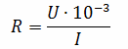
2.The resistance of the armature winding is measured by the ammeter-voltmeter method using a special two-contact probe with springs in the insulating handle (Fig. 8). The measurement is carried out as follows: a direct current from a well-charged battery with a voltage of 4-6 V is supplied to the collector plates of the stationary armature with the brushes removed. Between the plates to which the current is supplied, the voltage drop is measured with a millivoltmeter. The required resistance value of one branch of the armature
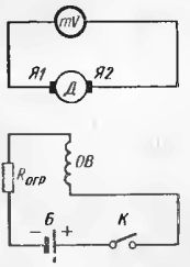
Rice. 6. Scheme for checking the correct installation of the brushes in the neutral position
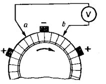
Rice. 7. Scheme for determining the polarity of the brushes
Rice. 8 Measurement of armature resistance using a two-pin probe
Similar measurements are made for all other plates. The resistance values between each adjacent plate should not differ from each other by more than 10% of the nominal value (if the machine has an equalizing winding, the difference can reach 30%).
The measurement of the insulation resistance of the windings and the inspection of the dielectric strength of the insulation of the windings are carried out in the same way as the corresponding inspection points of asynchronous motors.
The initial start-up of the DC motor is carried out immediately after tuning the motor to finally check its operability. Similar to asynchronous motors, DC motors are tested in idle mode with the mechanism and gearbox off. A similar idle test of the DC motor is necessary to properly tune the control circuit.
Starting the engine at idle and under load should be done very carefully.Immediately before starting, it is necessary to make sure that the armature rotates easily, the armature does not touch the stator, that there is grease in the bearings, and also check the protective relay. The tripping current of the maximum protection must not exceed 200% of the maximum motor current. With a test Starting a DC motor control commutation quality by monitoring the collector during current surges and then when the motor is idling at maximum voltage and maximum speed.
The load should not cause an increase in spark rate compared to idle. It is allowed to operate a DC motor with a degree of sparking of the brush 11/2 and even 2. At a more significant degree of sparking, the commutation is adjusted: the brushes are set to neutral, the coil of additional poles is correctly turned on, the brushes are pressed to the collector and the brushes adhere to the collector.
It should be remembered that unacceptable arcing on the collector can be associated with a malfunction of the control circuit, since the rate of change of the current in the armature and excitation circuits, the maximum values of current surges, the ratio of the armature current and the magnetic flux of the machine in different time depends on the circuit. After observing the operation under load and adjusting the commutation of the DC motor, the commissioning process can be considered complete.