Secondary Overcurrent Relay — RTM and RTV
 Direct -acting relays, directly acting on the switch drives, are built from two to four parts or more in many types of drives and are performed with or without delaying weather.
RTV overcurrent relay
The over -current relay with a PTV mechanical delay made on an electromagnetic system of solenoid type (Fig. 1) has a limited time characteristic.
When sufficient force appears in the relay coil, the anchor is drawn to the stationary pole. The force through the spring is transmitted to the drummer as a firm connection and pushes it up. The driver's movement is impeded by the clock mechanism to which it is connected by thrust. The speed of movement is determined amperage in the relay, which determines the dependent part of the characteristic (Fig. 2).
After the delay expires, the striker is released and, by hitting the roller shutdown lever, releases the switching mechanism.
Starting at currents about 3 times the operating current, a force sufficient to compress the spring is developed so that the core retracts immediately. In this case, the speed of movement of the striker is determined by the properties of the spring and the braking action of the mechanism and does not depend on the strength of the current in the relay, which provides an independent part of the characteristic.
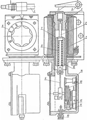
Rice. 1 Built-in relay type PTB: 1 — coil; 2 — drummer; 3 — fixed post (stop); 4 — stop roller; 5-lever of the stop roller; 6 — rotary tap switch; 7 — retaining ring; 8 — spiral spring; 9 — connecting rod of the clock mechanism and the core; 10 — adjusting screw for changing the delay; 11 — plate: 12 — lever; 13 — clock mechanism; 14 — watch case; 15 — core.
The setting of the operating current Iу is adjusted by changing the number of turns of the relay coil using a plug or rotary switch. If necessary, large settings are obtained by selecting the necessary branches with the number of turns ωset = ωcalculated. In which:
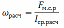
where FM.C.R — relay actuation magnetomotive force.
According to the technical data for the relay RTV FM.C.R = 1500 A, for RTM FM.C.R = 1350 A.
The time delay setting is adjusted using the clock set screw.
RTV relays have high consumption (20 … 50 V • A) and significant current errors (± 10%) and time delays (± 0.3 … 0.5 s in the independent part).
The relay drop rate depends on the relay operating time.The calculations take into account the return coefficient at the end of the clockwork coupling: 0.5 at the maximum time delay setting, 0.7 … 0.8 at the minimum.
Execution options.
PTB relays differ in setting limits and timing characteristics.
RTV relays built into PPM-10 drives and VMP-10P breaker drives have current setting limits of 5 … 10 (after 1 A), 11 … 20 (after 2 A) and 20 … 35 A .. .
The drive relays PP-61 and PP-67 have three modifications: PTB-I and PTB-IV with settings 5; 6; 7.5 and 10 A; Relays RTV-II and RTV-V-10; 12.5; 15; 17.5 A; Relays PTB-III and PTB-VI-20, 25, 30 and 35 A. In this case, unlike the previously described time characteristics of the relays PTB-I, PTB-II and PTB-III have an independent part with a current multiplier in the relay 1.6 … 1.8 or more.
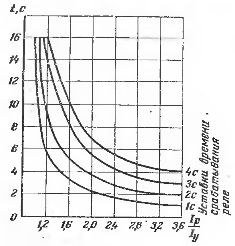
Rice. 2 Response time characteristics of the PTB type relay at different time settings
RTM overcurrent relay
The RTM instantaneous maximum current relay has no clock and differs from the RTV in a wide range of operating current settings (up to 150 A). There are instantaneous relay designs where the operating current is smoothly adjusted by changing the initial distance from the core to the stationary pole.
Thanks to simplicity of protection schemes with RTM and RTV relays direct acting, these relays are used for protection in rural power supply systems.
Electromagnetic solenoid actuators PS-10, PS-30 do not have built-in relay coils. In order to provide protection with power supply of working circuits directly from current transformers, a special device is used to the drive.
In addition to those mentioned earlier, an undervoltage relay with instantaneous action RNM and with time delay RNV is used.
Testing of secondary overcurrent relays.
When testing a PTB relay, the operating current scale is checked and time characteristics are taken, which can vary significantly even for a relay of the same type.
A feature of the PTB relay that must be taken into account during testing is the strong dependence of its resistance on the position of the core inside the coil and on the current flowing. For this reason, the power supply to the PTB relay in the test circuit (Fig. 3) is carried out by the secondary winding of the current transformer, the value of the secondary current of which changes slightly as the secondary load changes. In this case, the value of the primary current must be kept constant. The secondary windings of current transformers are connected in parallel to reduce the transformation ratio.
The operating current of the relay is determined by gradually increasing the current in the relay. The highest value at which the core releases the drive lock is measured.
The reverse current is determined by a smooth reduction of the current in the relay at the end of the actuating stroke with the clock mechanism.
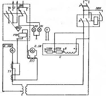
Rice.3 RTV Relay Test Circuit: R — Rack Power Switch; K — contactor; LTT-multiband laboratory current transformer; TT — current transformer for high voltage with two cores; RTV — a mechanical time-delay current relay built into the circuit breaker drive; 1BK, 3VK — closing the auxiliary contacts of the breaker drive (open when the position «Disabled» and closed when closed); 2VK — auxiliary contacts of the circuit breaker of the switch drive (interruption in the "On" position); LZ, LK — green and red lamps for signaling the «Disabled» and «Enabled» positions.
The response time of the protection with the PTB relay is measured from the moment the current is applied to the coil until the moment the contacts of the switch to which the timer is directly connected are opened. In the laboratory circuit, auxiliary contacts of the drive are used, opening in the «Off» position the circuit of the contactor coil, which acts as a switch.
Depending on the available equipment, instead of the K contacts of the contactor, the main contacts of the switch controlled by the drive with the PTB relay, which most accurately corresponds to the actual conditions, or directly the auxiliary contacts of the opening of the drive in the «Disabled» position can be used (eg 3VK and 4VK) which introduces a small error.