Ferroresonant voltage stabilizers - principle of operation
 The stabilizer, in which a stabilized voltage is obtained at the terminals of the nonlinear choke, is the simplest ferromagnetic stabilizer. Its main disadvantage is the low power factor. Also, at high currents in the circuit, the line choke sizes are very large.
To reduce weight and size, ferromagnetic voltage stabilizers are manufactured with a combined magnetic system, and to increase the power factor, a capacitor is included according to the current resonant circuit. Such a stabilizer is called ferroresonant.
Ferroresonant voltage stabilizers structurally similar to conventional transformers (Fig. 1, a). The primary winding w1, to which the input voltage Uin is applied, is located on section 2 of the magnetic circuit, which has a large cross-section, so that part of the magnetic circuit is in an unsaturated state. A voltage Uin creates a magnetic flux F2.
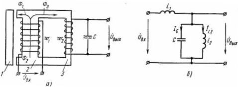
Rice. 1. Schematics of a ferroresonant voltage stabilizer: a — main; b — substitutions
The secondary winding w2, on the terminals of which the output voltage Uout is induced and to which the load is connected, is located in section 3 of the magnetic circuit, which has a smaller section and is in a saturated state. Therefore, with deviations of the voltage Uin and the magnetic flux F2, the value of the magnetic flux F3 in section 3 almost does not change, ee does not change. etc. v. secondary winding and Uout. As the flux F2 increases, that part of it that cannot pass through section 3 is closed through the magnetic shunt 1 (F1).
The magnetic flux F2 at a sinusoidal voltage Uin is sinusoidal. When the instantaneous value of the flux F2 approaches the amplitude, section 3 goes into the saturation mode, the flux F3 stops increasing and the flux F1 appears. Thus, the flux through the magnetic shunt 1 closes only at those moments when the flux F2 is close to the amplitude value. This makes the flux F3 non-sinusoidal, the voltage Uout also becomes non-sinusoidal, the third harmonic component is clearly expressed in it.
In the equivalent circuit (Fig. 1, b), the parallel-connected inductance L2 of the non-linear element (secondary winding) and capacitance C form a ferroresonant circuit with the characteristics shown in Fig. 2. As can be seen from the equivalent circuit, the currents in the branches are proportional to the voltage Uin. Curves 3 (branch L2) and 1 (branch C) are located in different quadrants because the currents in the inductance and capacitance are opposite in phase. Characteristic 2 of the resonant circuit is constructed by algebraically summing the currents in L2 and C at the same voltage values Uout.
As can be seen from the characteristics of the resonant circuit, the use of a capacitor makes it possible to obtain a stable voltage at low magnetizing currents, i.e. at lower voltage Uin.
In addition, with a capacitor, the regulator operates with a high power factor. As for the stabilization factor, it depends on the angle of inclination of the horizontal part of curve 2 to the abscissa axis. Since this section has a significant angle of inclination, it is impossible to obtain a large stabilization factor without additional devices.
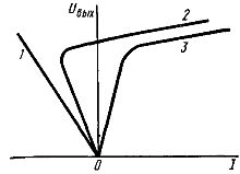
Rice. 2. Characteristics of a nonlinear element of a ferroresonant voltage stabilizer
Such an additional device is the compensating coil wk (fig.3), located together with the primary coil on the unsaturated section 1 of the magnetic circuit. As Uin and F increase, the emf increases. etc. v. compensating coil. It is connected in series with the secondary winding, but so e. etc. c. the compensating coil was opposite in phase e. etc. v. secondary winding. If Uin increases, then the emission increases slightly. etc. v. secondary winding. Voltage Uout which is determined by the difference in e. etc. c. the secondary and compensating windings are kept constant due to the increase in e. etc. v. compensating coil.
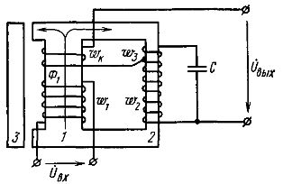
Rice. 3. Scheme of a ferroresonant voltage stabilizer with a compensation coil
The winding w3 is designed to increase the voltage across the capacitor, which increases the capacitive component of the current, the stabilization factor and the power factor.
The disadvantages of ferroresonant voltage stabilizers are the non-sinusoidal output voltage and its frequency dependence.
The industry produces ferroresonant voltage stabilizers with power from 100 W to 8 kW, with a stabilization factor of 20-30. In addition, ferroresonant stabilizers without a magnetic shunt are produced. The magnetic flux F3 in them is closed to air, that is, it is a leakage flux. This makes it possible to reduce the weight of the stabilizer, but narrows the working area to 10% of the nominal value Uin at a stabilization factor kc equal to five.