Thyristor DC / DC converters
 Thyristor DC / DC converter (DC) is a device for converting alternating current into direct current with regulation according to a given law of the output parameters (current and voltage). Thyristor converters are designed to power armature circuits of motors and their field windings.
Thyristor converters consist of the following basic units:
• a transformer or current-limiting reactor on the AC side,
• rectifier blocks,
• smoothing reactors,
• elements of the control, protection and signaling system.
The transformer matches the input and output voltages of the converter and (like the current-limiting reactor) limits the short-circuit current in the input circuits. Smoothing reactors are designed to smooth the ripples of the rectified voltage and current. Reactors are not provided if the load inductance is sufficient to limit the ripple within certain limits.
The use of thyristor DC-DC converters allows to realize practically the same electric drive characteristics as when using rotary converters in generator-motor systems (D — D), that is, to adjust the speed and torque of the engine over a wide range, to obtain special mechanical characteristics and the desired nature of the transients when starting, stopping, reversing, etc.
However, compared to rotary static converters, they have a number of known advantages, which is why static converters are preferred in new developments of crane electric drives. Thyristor DC-DC converters are the most promising for use in electric drives of crane mechanisms with a power of more than 50-100 kW and mechanisms where it is required to obtain special characteristics of the drive in static and dynamic modes.
Rectification schemes, principles of construction of power circuits of converters
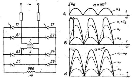
Thyristor converters are made with single-phase and multi-phase corrective circuits… There are several design ratios for the basic rectification schemes. One of these schemes is shown in fig. 1, a. Regulation of voltage Va and current Ia produced by changing the control angle α... In fig. 1, b-e, for example, the nature of the change of currents and voltages in a three-phase zero-rectification circuit with an active-inductive load is shown
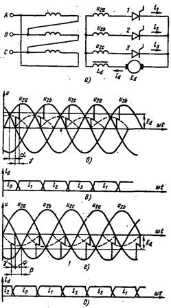
Rice. 1. Three-phase neutral circuit (a) and diagrams of current and voltage changes in the rectifier (b, c) and inverter (d, e) modes.
The angle shown in the diagrams γ (switching angle) characterizes the time period during which the current flows simultaneously through two thyristors. Dependence of the average value of the adjusted voltage Вa on the adjustment angle α is called the control characteristic.
For neutral circuits, the average rectified voltage is given by the expression
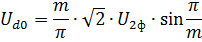
where m — the number of phases of the secondary winding of the transformer; U2f is the rms value of the phase voltage of the secondary winding of the transformer.
For bridge circuits Udo 2 times higher, because these circuits are equivalent to series connection of two zero circuits.
Single-phase correction circuits are used, as a rule, in circuits with relatively large inductive resistances. These are circuits of independent excitation windings of motors, as well as armature circuits of low-power motors (up to 10-15 kW). Polyphase circuits are mainly used for casting armature circuits of motors with a power of more than 15–20 kW and less often for powering field windings. Compared to single-phase, polyphase rectifier circuits have a number of advantages. The main ones are: lower pulsation of the rectified voltage and current, better use of the transformer and thyristors, symmetrical loading of the phases of the supply network.
In thyristor DC-DC converters intended for crane drives with a power of more than 20 kW, the use of three-phase bridge circuit… This is due to the good use of the transformer and thyristors, the low ripple level of the rectified voltage and current, and the simplicity of the transformer circuit and design.A well-known advantage of a three-phase bridge circuit is that it can be made not with a transformer connection, but with a current-limiting reactor, the dimensions of which are significantly smaller than the dimensions of the transformer.
In a three-phase neutral circuit, the conditions for using the transformer with commonly used connection groups D / D and Δ / Y are worse due to the presence of a constant component of the flux. This leads to an increase in the cross-section of the magnetic circuit and, accordingly, the design power of the transformer. To eliminate the constant component of the flux, a zigzag connection of the secondary windings of the transformer is used, which also somewhat increases the design power. The increased level, ripple of the rectified voltage, together with the drawback noted above, limits the use of a three-phase neutral circuit.
A six-phase reactor circuit is recommended when used for low voltage and high current because in this circuit the load current flows in parallel rather than in series through two diodes as in a three-phase bridge circuit. The disadvantage of this circuit is the presence of a smoothing reactor with a typical power of about 70% of the corrected rated power. In addition, a rather complex transformer design is used in six-phase circuits.
Rectifier circuits based on thyristors provide operation in two modes — rectifier and inverter. When operating in inverter mode, the energy from the load circuit is transferred to the supply network, that is, in the opposite direction compared to the rectifier mode, therefore, when inverting, the current and e. etc. c. the windings of the transformer are directed oppositely, and when straightened - in accordance.The current source in inverting mode is e. etc. c. load (DC machines, inductance) that must exceed the inverter voltage.
The transfer of the thyristor converter from the rectifier mode to the inverter mode is achieved by changing the polarity of e. etc. c. increasing the load and the angle α above π / 2 with an inductive load.
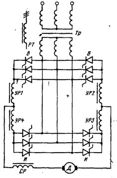
Rice. 2. Anti-parallel circuit for switching on groups of valves. UR1 — UR4 — leveling reactors; RT — current-limiting reactor; CP — smoothing reactor.
Rice. 3. Scheme of irreversible TP for circuits of excitation windings of motors. To ensure inversion mode, it is necessary that the next closing thyristor has time to restore its blocking properties while there is a negative voltage on it, that is, in the angle φ (Fig. 1, c).
If this does not happen, then the closing thyristor can reopen as a forward voltage is applied to it. This will cause the inverter to overturn, where an emergency current will occur, as e.g. etc. c. DC machines and transformer will match in direction. To avoid a rollover, the condition is required

where δ — the angle of restoration of the locking properties of the thyristor; β = π — α This is the lead angle of the inverter.
Power circuits of thyristor converters, intended for powering the armature circuits of motors, are made in both irreversible (one rectifier group of thyristors) and reversible (two rectifier groups) versions. Irreversible versions of thyristor converters, providing unidirectional conduction, allow operation in motor and generator modes in only one direction of motor torque.
To change the direction of the moment, it is necessary either to change the direction of the armature current with the direction of the field flux constant, or to change the direction of the field flux while maintaining the direction of the armature current.
Inverting thyristor converters have several types of power circuit diagrams. The most common is the scheme with anti-parallel connection of two groups of valves to one secondary winding of the transformer (Fig. 2). Such a scheme can be implemented without a separate transformer by feeding thyristor groups from a common alternating network through anode current limiters of RT reactors. The transition to the reactor version significantly reduces the size of the thyristor converter and reduces its cost.
Thyristor converters for winding circuits of motor fields are mainly made in irreversible construction. In fig. 3a shows one of the rectifier switching circuits used. The circuit allows you to vary the excitation current of the motor over a wide range. The minimum value of the current occurs when the thyristors T1 and T2 are closed, and the maximum when they are open. In fig. 3, b, d shows the nature of the change in rectified voltage for these two states of thyristors, and in Fig. 3, in for the condition when
Control methods for inverting thyristor converters
In inverting thyristor converters, there are two main ways of controlling the valve groups — joint and separate. Co-management, on the other hand, is done consistently and inconsistently.
With coordinated control, shooting pulses thyristors are applied to the two groups of valves in such a way that the average values of the corrected voltage for the two groups are equal to each other. This is provided on condition

where av and ai — the adjustment angles of the groups of rectifiers and inverters. In the case of inconsistent control, the average voltage of the inverter group exceeds the voltage of the rectifier group. This is achieved under the condition that

The instantaneous value of the group voltages with joint control are not equal to each other at all times, as a result of which in a closed loop (or circuits) formed by thyristor groups and transformer windings, an equalizing current flows to limit which equalization reactors UR1-UR4 are included in the thyristor converter (see Fig. 1).
The reactors are connected to the equalizing current loop, one or two per group, and their inductance is chosen so that the equalizing current does not exceed 10% of the rated load current. When the current limiting reactors are switched on, two per group, they saturate when the load current flows. For example, during group B operation, reactors UR1 and UR2 are saturated, while reactors URZ and UR4 remain unsaturated and limit the equalizing current. If the reactors are on, one per group (UR1 and URZ), they are not saturated when the payload is flowing.
Converters with inconsistent control have smaller reactor sizes than with coordinated control.However, with inconsistent control, the range of permissible control angles decreases, which leads to a worse use of the transformer and a decrease in the power factor of the installation. At the same time, the linearity of the control and speed characteristics of the electric drive is violated. Separate control of groups of valves is used to completely eliminate equalizing currents.
Separate control consists in the fact that the control pulses are applied only to the group that should be working at the moment. Control pulses are not supplied to the valves of the idle group. To change the operating mode of the thyristor converter, a special switching device is used, which, when the current of the thyristor converter is zero, first removes the control pulses from the previous working group, and then, after a short pause (5-10 ms), sends control pulses to the other group.
With separate control, there is no need to include equalizing reactors in the circuit of separate groups of valves, the transformer can be fully used, the probability of the inverter overturning due to a decrease in the operating time of the thyristor converter in inverter mode is reduced, energy losses are reduced and accordingly the efficiency of the electric drive increases due to the absence of equalizing currents. Separate control, however, places high demands on the reliability of devices for blocking control pulses.
Malfunction in the operation of blocking devices and the appearance of control pulses on a non-working thyristor group lead to an internal short circuit in the thyristor converter, since the equalizing current between the groups in this case is limited only by the reactance of the transformer windings and reaches an unacceptably large value.