Repair of oil switches
 The repair of oil switches is mainly reduced to regular maintenance and, if necessary, replacing worn parts with new ones from the number of spare parts. Do-it-yourself repair of damaged parts is not recommended, except as noted below.
Maintenance of oil switches
During work high voltage circuit breakers are subject to periodic scheduled inspections. After an accident or a long stay in the disconnected state, unscheduled checks are carried out in accordance with PTE, "Technical Safety Rules" (PTB) and factory instructions.
When reviewing, pay particular attention to:
1. oil level in the switch poles,
2. no oil discharge in the oil buffer area,
3. Leaking oil from the pole cylinders,
4. excessive overheating
5. the state of external contact connections, insulation and grounding,
6. dust, pollution,
7. presence of cracks on insulators and breakers.
Maintenance of oil switches
The oil switch, regardless of the type, is cleaned of dust, the porcelain insulators and insulating parts are wiped with a cloth slightly moistened with alcohol, the lubrication of the rubbing surfaces is restored, the presence of oil in the oil buffers and cylinders (pillars) ) is checked and , if necessary, is supplemented or replaced with fresh ones.
In case of oil leakage, tighten the bolt connections. Check pole resistance and grounding. To add oil to the oil buffer of the VMG-10 switch, proceed as follows (Fig. 2): unscrew the nut 3, remove the piston 5 and the spring 6. The oil level from the bottom of the cylinder 7 should be 45 mm. Then collect the buffer and manually check the smooth movement of the stem 4.
Overhaul of oil switches includes the following basic works:
1. disconnecting the circuit breaker from the busbars and the drive,
2. oil drain,
3. disassembling the switch,
4. Inspection and repair of the actuator, porcelain support, bushings and pull insulators, insulation in the tank, arc extinguishing chamber, fixed sockets and movable contacts, insulating cylinders, oil indicators, seals and other parts.
Disassembly of the VMG-10 switch is carried out in the following sequence:
1. remove the rod (axis) 1 hinged (Fig. 3) tip 4 of the movable contact with the rod,
2. the contact is separated from the rod,
3. unscrew the thrust bolts and cylinders 1 (see fig. 1),
4. removed from the support insulators that remain on the frame,
5. unscrew the bolts and disconnect the flexible connection 3 (fig. 3),
6. remove the removable contact together with the terminal block 2 and the flexible connection,
7.Unscrew the bolts on the flange of the sleeve, which is removed together with the bracket,
8. the internal insulating parts of the cylinder are disassembled (fig. 4).
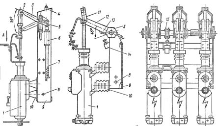
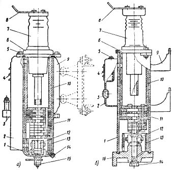
Rice. 1. Oil switch: a-VMG-133, b-VMG-10; 1 - cylindrical, 2 - porcelain rod; 3 — lever with two arms, 4 — spring buffer, 5 — bearing, 6 — oil buffer, 7 — stop spring, 8 — ground bolt, 9 — frame, 10 — support insulator, 11 — clamp, 12 — isolation lever, 13.14 — locking bolts (lock «on»), 15 - the same, for the middle connection with the drive
When disassembling the VMG-133 pole, remove the upper cylinder 10, then the chamber 11 and the lower cylinder 13. Remove the cylinder carefully so as not to damage the varnish coatings. Then remove the fixed contact 12 of the socket, having previously unscrewed the nut 15. To prevent the socket from turning, the pin is held by the flats with a key. Remove the support ring and the plywood gasket.
Distinctive features of the device, disassembly and repair breaker VMG-10… Instead of a porcelain finned rod, the switch has a double-armed insulating lever 12, which is connected to the movable contact by means of a clamp 11 (see Fig. 1).
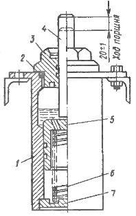
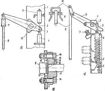
Rice. 2. Oil buffer of the breaker VMG -10: 1 — housing, 2 — sealing gasket, 3 — special nut, 4 — rod, 5 — piston, 6 — spring, 7 — bottom of the housing
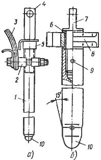
Rice. 3. Movable contact: a — switch VMG -10, b — the same, VMPP -10; 1 — rod, 2 — pin block, 3 — flexible link, 4 — tip with ears, 5 — lock nut, 6 — sleeve, 7 — head, 8 — guide block, 9 — pin, 10 — tip
The end positions of the switch are limited by the rollers of the double arm lever 3 (Fig. 5), welded to the shaft 2 between the end and middle main levers.One of the rollers fits the bolt 7 («on»), the other — to the rod of the oil buffer 4 («off»).
The buffer spring 5 of the switch is fixed on the middle lever with two arms.
The cylinder has top and bottom covers allowing inspection of socket contact without completely disassembling the master cylinder.
The most vulnerable components of the circuit breaker—the fixed socket contact and the arc chute—are removed from the cylinder below without disassembling the sleeve. In assembly, the arc chute is inserted into the breaker cylinder below.
Rice. 4. Cylinder (pole): a — breaker VMG -133, b — the same, VMG -10; 1 — main cylinder, 2 — additional tank, 3 — oil indicator, 4 — louvers, 5 — oil filler plug, 6 — upper cover, 7 — sleeve, 8 — clamps, 9 — clamp, 10 — upper bakelite cylinder , 11 — arc chamber, 12 — internal (fixed) contact, 13 — bottom bakelite cylinder, 14 — oil drain plug, 15 — pin and nut, 16 — bottom cover
Rice. 5. Drive mechanism: a — switch VMG-10, b — the same, VMG-133, c — bearing; 1 — frame, 2 — shaft, 3 — lever with two arms, 4 — oil buffer, 5 — spring buffer, 6 — opening spring, 7 — locking bolt, 8 — movable contact, 9 — axis, 10 — clamp, 11 — insulating lever (porcelain rod), 12 — bearing, 13 — cutout in the frame for installing the shaft, 14 — bolt with nut and washer, 15 — lubrication hole, 16 — washers, 17 — shaft
To facilitate installation, the protruding parts of the cardboard sleeve are pre-lubricated with a thin layer of grease. The difference between the bottom surface of the arc chute and the top of the socket contact should be within 2–5 mm, which is easily determined by direct (not indirect) measurement.
Distinctive features of the device, disassembly and repair of circuit breakers VMP-10 and VMPP-10 (Fig. 6). The VMP-10 switch is structurally different from the VMG-10. The «on» and «off» mechanisms are in the pole of the switch, there are no flexible connections, the movable contact does not extend beyond the pole, there is no output insulator with insulating parts and springs.
Current collection is carried out by rollers, the poles of the switch are mounted on a common welded frame, which is the base of the switch. Inside the frame are located: shaft, release springs, oil and spring buffer. The pole consists of an insulating cylinder with reinforced metal flanges at the ends. The contact wires of the switch have a corrosion-resistant galvanic coating.
This circuit breaker is widely used with different types of actuators, for example PP-67, PE-11 in distribution cabinets.
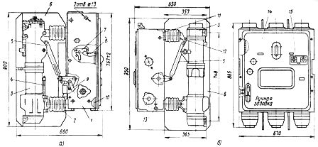
Rice. 6. Oil switches; a — VMP -10, b — VMPP -10; 1 — frame, 2, 12 — supporting insulator, 3 — pole, 4 — manometer, 5 — insulating rod, 6 — insulating partition, 7, 8 — paws, 9, 10 — rods, 11 - frame with built-in spring relay protection of the drive and the block, 13 — grounding bolt, 14 — cover, 15 — «off» and «on» button
The VMPP-10 switch and its drive are combined and built into a common frame. The pole (Fig. 7) is very similar to the VMP-10 pole. It consists of an insulating cylinder 3, at the ends of which metal flanges 2 and 4 are reinforced. On the upper flange, the body 5 is fixed, to which the pole head 6 is attached.
The mechanism for moving the movable contact is located inside the housing and consists of an internal 12 and an external 15 and 16 lever, firmly attached to a common shaft 14.The outer lever is connected to the drive shaft by means of an insulating rod, and the inner one is rotatably connected to the movable contact by two clamps 25 at the upper end, which the guide block 8 and the head 7 are fixed (see Fig. 3) to secure the contact to the shackles of the mechanism .
The lower end of the movable contact is connected to the rail in which the sleeve 6 is mounted to guide the movement of the movable contact. Buffers are mounted on the piston to soften the shock when shutting down. The rollers 18 (Fig. 7), sliding between two guides 17, center the inclusion of the movable contact 24 in the socket (fixed) and are current collecting devices for transferring current from the movable contact to the guide rods and further to the upper outer part contact 6. A plug 8 is provided in the head for filling oil and for passing the measuring rod.
To repair damaged elements of the switch, partial or complete disassembly is required, which is carried out as follows:
• it is necessary to remove the interpolar barriers,
• drain the oil from the pillars,
• turn off the lower rails,
• remove the bottom covers with fixed socket contacts,
• remove the arc chute 21 and the distance cylinders 23 (fig. 7).
• Wash the removed parts with oil and check.
• Turn the switch to the «on» position and check the tip of the movable contact.
To replace or repair the movable contact, additional disassembly of the pole is required, for which, disconnect the upper tires, remove the housing with the mechanism, having previously disconnected it from the insulating cylinder and the insulating rod, remove the bus 20 and remove the rollers down wires. Move the mechanism to the «off» position and disconnect the locking bus and the movable contact 24.The cylinder is assembled in reverse order.
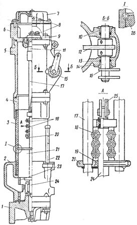
Rice. 7. VMPP -10 switch pole: 1 — lower cover, 2 — lower flange, 3 — cylinder, 4 — upper flange, 5 — housing, 6 — head, 7 — upper cover, 8 — oil filler plug, 9 — valve , 10 — bearing, 11 — buffer, 12 — inner arm of the mechanism, 13 — seal, 14 — shaft of the mechanism, 15 — mechanism, 16 — outer arm of the mechanism, 17 — guide rod, 18 — down wires ( 4 down wires for 20 kA and 6 for 31.5 kA for a circuit breaker with a rated current of 630 A, 6 for 1000 A and 10 for 1600 A), 19 — sleeve, 20 — bar, 21 — arc chamber, 22 — oil indicator , 23 — spacer cylinder, 24 — movable rod, 25 — earring, 26 — spring.
Continuation of the article: Repair of separate assemblies and parts of oil switches