High voltage switches: classification, device, principle of operation
The requirements for the switches are as follows:
 1) reliability at work and safety for others;
2) quick response — possibly short shutdown time;
3) ease of maintenance;
4) ease of installation;
5) silent operation;
6) relatively low cost.
The currently used circuit breakers meet the listed requirements to a greater or lesser extent. Circuit breaker designers, however, strive to better match circuit breaker characteristics with the above requirements.
Oil switches
 There are two types of oil switches — reservoir and low oil. The arc space deionization methods in these switches are the same. The only difference is in the insulation of the contact system from the ground base and in the amount of oil.
Until recently, tanks for tanks of the following types worked: VM-35, S-35, as well as switches of the U series with voltages from 35 to 220 kV. Tank switches are designed for external mounting, not currently in production.
The main disadvantages of tank switches: explosion and fire; the need for periodic monitoring of the condition and level of oil in the tank and inlets; a large volume of oil, which leads to a large investment of time for its replacement, the need for large reserves of oil; not suitable for indoor installation.
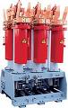
Low oil switches
Low-oil switches (pot type) are widely used in closed and open switchgear all voltages. The oil in these switches serves mainly as an arcing medium and only partially as insulation between open contacts.
Isolation of live parts from each other and from grounded structures is done with porcelain or other solid insulating materials. The contacts of the switches for internal mounting are located in a steel tank (pot), which is why the name of "pot type" switches is retained.
Low-oil circuit breakers of voltage 35 kV and above have a porcelain body. The most widely used are pendants of the 6-10 kV type (VMG-10, VMP-10). In these circuit breakers the body is fixed on porcelain insulators to a common frame for the three poles. Each pole has one contact break and an arc chute.
Design schemes of low-oil switches 1 — movable contact; 2 — arc chute; 3 — fixed contact; 4 — working contacts
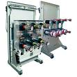
 At high rated currents, it is difficult to operate with one pair of contacts (acting as operating and arcing contacts), therefore the operating contacts are provided outside the breaker and the arcing contacts are in a metal tank. At high breaking currents, there are two arcing breaks for each pole. According to this scheme, switches of the MGG and MG series are made for voltages up to and including 20 kV.Massive external operating contacts 4 allow the circuit breaker to be designed for high rated currents (up to 9500 A). For voltages of 35 kV and above, the switch body is made of porcelain, the VMK series is a column switch with low oil). In automatic circuit breakers 35, 110 kV, one interruption per pole is provided, at high voltage — two or more interruptions.
Disadvantages of low-oil switches: risk of explosion and fire, although much less than that of tank switches; inability to implement high-speed automatic closing; the need for periodic control, topping up, relatively frequent oil change in arc tanks; the difficulty of installing built-in current transformers; relatively low breaking capacity.
The field of application of low-oil circuit breakers is closed switchgears of power plants and substations 6, 10, 20, 35 and 110 kV, complete switchgears 6, 10 and 35 kV and open switchgears 35 and 110 kV.
See here for more details: Types of oil switches
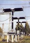
Air switches
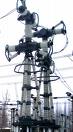 Air circuit breakers for voltages of 35 kV and above are designed to break large short-circuit currents. Air is turned on voltage 15 kV is used in power plants as a generator. Their advantages: quick response, high breaking capacity, insignificant burning of contacts, lack of expensive and insufficiently reliable bushings, fire safety, less weight compared to oil switches in the tank. Disadvantages: the presence of cumbersome air economy, danger of explosion, lack of built-in current transformers, the complexity of the device and operation.
In air switches, the arc is extinguished with compressed air at a pressure of 2-4 MPa, and the insulation of live parts and the arc extinguishing device is made with porcelain or other solid insulating materials. The design schemes of air switches are different and depend on their voltage rating, the method of creating an insulating gap between the contacts in the off position, and the method of supplying compressed air to the arc extinguishing device.
High rated circuit breakers have a main and arcing circuit similar to low oil MG and MGG circuit breakers. The main part of the current in the closed position of the switch passes through the main contacts 4, which are located open. When the switch is turned off, the main contacts first open, then all the current passes through the arc contacts closed in chamber 2. While these contacts open, compressed air from tank 1 is fed into the chamber, a powerful blast is created, extinguishing the arc. Blowing can be longitudinal or transverse.
The necessary insulation gap between the contacts in the open position is created in the arc chute by separating the contacts by a sufficient distance. The switches made according to the project with an open separator are produced for indoor installation for voltages 15 and 20 kV and currents up to 20,000 A (VVG series). With this type of switches, after disconnecting the separator 5, the supply of compressed air to the chambers is stopped and the arcing contacts are closed.
Construction diagrams of air switches 1 — tank for compressed air; 2 — arc chute; 3 — shunting resistor; 4 — main contacts; 5 — separator; 6 — capacitive voltage divider for 110 kV — two breaks per phase (d)
In air circuit breakers for open installation for voltage 35 kV (VV-35), it is sufficient to have one interruption per phase.
In switches with a voltage of 110 kV and more, after the arc is extinguished, the contacts of the separator 5 open and the separator chamber remains full of compressed air all the time in the off position. In this case, compressed air is not supplied to the arc chute and the contacts in it are closed.
Circuit breakers of the VV series for voltages up to 500 kV are created according to this design scheme. The higher the rated voltage and the higher the limiting power, the more interruptions there must be in the arc chute and in the separator.
Air-filled circuit breakers of the VVB series are made according to the design scheme in Fig., D. The voltage of the VVB module is 110 kV at a pressure of compressed air in the fire extinguishing chamber of 2 MPa. The rated voltage of the VVBK circuit breaker module (large module) is 220 kV and the air pressure in the extinguishing chamber is 4 MPa. Circuit breakers of the VNV series have a similar design scheme: a module with a voltage of 220 kV at a pressure of 4 MPa.
For circuit breakers of the VVB series, the number of arc chutes (modules) depends on the voltage (110 kV — one; 220 kV — two; 330 kV — four; 500 kV — six; 750 kV — eight), and for large circuit breaker modules (VVBK, VNV), modules with numbers twice less, respectively.
Circuit breakers SF6
 SF6 gas (SF6 — sulfur hexafluoride) is an inert gas with a density 5 times greater than that of air. The electrical strength of SF6 gas is 2-3 times higher than the strength of air; at a pressure of 0.2 MPa, the dielectric strength of SF6 gas is comparable to that of petroleum.
In SF6 gas at atmospheric pressure, an arc can be extinguished with a current that is 100 times higher than the current interrupted in air under the same conditions. The exceptional ability of SF6 gas to extinguish the arc is explained by the fact that its molecules capture the electrons of the arc column and form relatively immobile negative ions. The loss of electrons makes the arc unstable and easily extinguished. In a flow of SF6 gas, that is, during gas jetting, the absorption of electrons from the arc column is even more intense.
 SF6 circuit breakers use auto-pneumatic (auto-compressing) arc extinguishing devices where gas is compressed by a piston device during tripping and directed into the arcing area. The SF6 circuit breaker is a closed system with no gas emissions to the outside.
Currently, SF6 circuit breakers are used for all voltage classes (6-750 kV) at a pressure of 0.15 — 0.6 MPa. Increased pressure is used for switches with higher voltage classes. SF6 circuit breakers of the following foreign companies have proven themselves well: ALSTOM; SIEMENS; Merlin Guerin and others. The production of modern SF6 circuit breakers of PO «Uralelectrotyazmash» is mastered: tank circuit breakers of the VEB, VGB series and column switches of the VGT, VGU series.
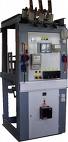
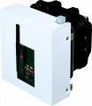
As an example, consider the design of a 6-10 kV LF circuit breaker by Merlin Gerin.
The basic circuit breaker model consists of the following elements:
— the body of the circuit-breaker, in which all three poles are located, representing a "pressure vessel", filled with SF6 gas at a low excess pressure (0.15 MPa or 1.5 atm);
— mechanical drive type RI;
— actuator front panel with manual spring loading handle and spring and circuit breaker status indicators;
— contact pads for high voltage power supply;
— multi-pin connector for connecting secondary switching circuits.
Vacuum circuit breakers
The dielectric strength of vacuum is significantly higher than that of other media used in circuit breakers. This is explained by the increase in the mean free path of electrons, atoms, ions and molecules with a decrease in pressure. In a vacuum, the mean free path of the particles exceeds the dimensions of the vacuum chamber.
1/4" gap recovery dielectric strength after 1600 A current cut-off in vacuum and various gases at atmospheric pressure
 Under these conditions, particle impacts on the chamber walls occur much more often than particle-to-particle collisions. The figure shows the dependence of the breakdown voltage of vacuum and air on the distance between electrodes with a diameter of 3/8 « tungsten. With such a high dielectric strength, the distance between the contacts can be very small (2 — 2.5 cm ), so the chamber dimensions can also be relatively small...
The process of restoring the electrical strength of the gap between the contacts when the current is off occurs in vacuum much faster than in gases. The level of vacuum (residual gas pressure) in modern industrial arc ducts is usually Pa. In accordance with the theory of the electrical strength of gases, the required insulating properties of the vacuum gap are also achieved at lower vacuum levels (of the order of Pa), but for the current level of vacuum technology, the creation and maintenance of the Pa level throughout life of the vacuum chamber is not a problem.This provides the vacuum chambers with reserves of electrical strength for the entire service life (20-30 years).
A typical vacuum circuit breaker design is shown in the figure.
Block diagram of a vacuum breaker
The design of the vacuum chamber consists of a pair of contacts (4; 5), one of which is movable (5), enclosed in a vacuum-tight shell welded by ceramic or glass insulators (3; 7), upper and lower metal covers (2; 8) ) and metal shield (6). The movement of the movable contact relative to the fixed one is ensured by means of a sleeve (9). The camera cables (1; 10) are used to connect it to the main switch circuit.
It should be noted that only special vacuum-resistant metals, purified from dissolved gases, copper and special alloys, as well as special ceramics are used for the manufacture of the vacuum chamber housing. The contacts of the vacuum chamber are made of a metal-ceramic composition (as a rule, it is copper-chromium in a ratio of 50%-50% or 70%-30%), which provides high breaking capacity, resistance to wear and prevents the appearance of welding points on the contact surface. Cylindrical ceramic insulators, along with a vacuum gap at open contacts, provide isolation between the chamber terminals when the switch is off.
Tavrida-electric has released a new design vacuum circuit breaker with a magnetic lock. Its design is based on the principle of aligning the driving electromagnet and the vacuum breaker in each pole of the breaker.
The switch closes in the following sequence.
In the initial state, the contacts of the vacuum interrupter chamber are open due to the action of the closing spring 7 on them through the pull insulator 5. When a voltage of positive polarity is applied to the coil 9 of the electromagnet, the magnetic flux accumulates in the gap of the magnetic system.
At the moment when the compressive force of the armature created by the magnetic flux exceeds the force of the stop spring 7, the armature 11 of the electromagnet, together with the traction insulator 5 and the movable contact 3 of the vacuum chamber, begins to move up, compressing the spring for stopping. In this case, a motor-EMF occurs in the winding, which prevents a further increase in current and even somewhat reduces it.
In the process of movement, the armature gains a speed of about 1 m / s, which avoids preliminary damage when switching on and eliminates the bouncing of the VDK contacts. When the vacuum chamber contacts are closed, an additional compression gap of 2 mm remains in the magnetic system. The speed of the armature drops sharply, since it also has to overcome the spring force of the additional preload of the contact 6. However, under the influence of the force created by the magnetic flux and inertia, the armature 11 continues to move up, compressing the spring for stop 7 and an additional spring for preloading contacts 6.
At the moment of closing the magnetic system, the armature contacts the upper cover of the drive 8 and stops. After the closing process, the current to the drive coil is turned off. The switch remains in the closed position due to the residual induction created by the ring permanent magnet 10, which holds the armature 11 in a pulled position to the upper cover 8 without additional current supply.
To open the switch, a negative voltage must be applied to the coil terminals.
 Currently, vacuum circuit breakers have become the dominant devices for electrical networks with a voltage of 6-36 kV. Thus, the share of vacuum circuit breakers in the total number of manufactured devices in Europe and the USA reaches 70%, in Japan - 100%. In Russia, in recent years, this share has had a constant upward trend, and in 1997 it exceeded the 50% mark. The main advantages of explosives (compared to oil and gas switches) that determine the growth of their market share are:
— higher reliability;
— lower maintenance costs.
See also: High Voltage Vacuum Circuit Breakers — Design and Principle of Operation