High Voltage Vacuum Circuit Breakers — Design and Principle of Operation
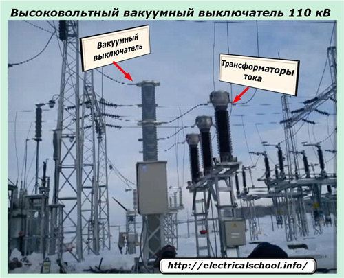
Among modern high-voltage equipment designed for switching electrical circuits in electricity, a special place is allocated to vacuum circuit breakers. They are widely used in networks from 6 to 35 kV and less often in schemes from 110 or 220 kV inclusive.
Their rated breaking current can be from 20 to 40 kA, and their electrodynamic resistance is about 50 ÷ 100. The total tripping time of such a circuit breaker or failure is about 45 milliseconds.
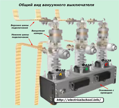
Each phase of the circuit is reliably separated by insulators and at the same time all equipment is structurally assembled on one common drive. The substation busbars are connected to the input terminals of the switch and the output connection to the output terminals.
Power contacts operate within the vacuum circuit breaker which are pressed together to provide minimum contact resistance and reliable passage of both load and emergency currents.
The upper part of the contact system is permanently fixed, and the lower part under the action of the driving force is able to move strictly in the axial direction.
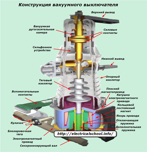
The picture shows that the contact plates are located in a vacuum chamber and are driven by rods controlled by the tension forces of the springs and coils of the electromagnets. This entire structure is located inside a system of insulators, excluding the occurrence of leakage currents.
The walls of the vacuum chamber are made of purified metals, alloys and special ceramic compositions that ensure the hermeticity of the working environment for several decades. In order to exclude the ingress of air during the movements of the movable contact, a sleeve device is installed.
The armature of a DC electromagnet can move to close the power contacts or break them due to a change in the polarity of the voltage applied to the coil. A permanent circular magnet built into the drive structure holds the moving part in any actuated position.
The system of springs ensures the creation of optimal movement speeds of the armature during commutations, exclusion of contact bounce and the possibility of collapses in the wall structure.
The kinematic and electrical circuits with a synchronizing shaft and additional auxiliary contacts are assembled inside the switch body, providing the ability to monitor and control the position of the switch in any state.
Appointment
In terms of its functional tasks, the vacuum breaker does not differ from other analogues of high-voltage equipment. Provides:
1.Reliable passage of rated electrical power during continuous operation;
2. the possibility of guaranteed equipment switching by electrical personnel in manual or automatic mode during operational switching to change the configuration of the working circuit;
3. automatic removal of emerging accidents in the shortest possible time.
The main difference between the vacuum circuit breaker is the method of extinguishing the electric arc that occurs when the contacts are disconnected during shutdown. If its analogues create an environment for compressed air, oil or SF6 gas, then a vacuum works here.
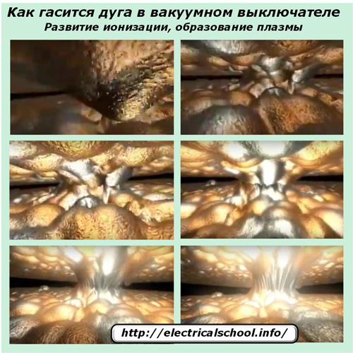
The principle of arc extinguishing in the power circuit
Both contact plates operate in a vacuum environment formed by pumping gases from the arc chute vessel to 10-6÷10-8 N / cm2. This creates a high dielectric strength characterized by improved dielectric properties.
With the start of movement from the drive of the contacts, a gap appears between them, which immediately contains a vacuum. Inside it, the process of evaporation of the heated metal from the contact pads begins. Load current continues to flow through these pairs. It initiates the formation of additional electrical discharges, creating an arc in a vacuum environment, which continues to develop due to the evaporation and release of metal vapors.
Under the action of the applied potential difference, the formed ions move in a certain direction, creating a plasma.
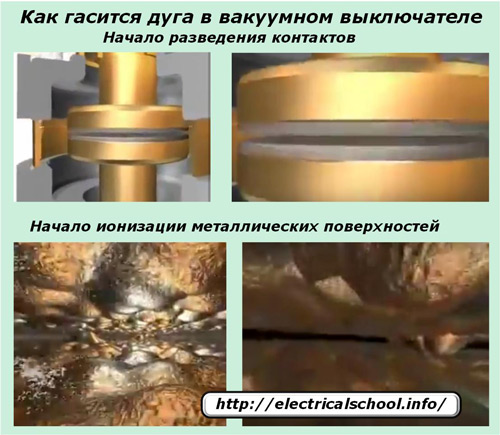
In its environment, the flow of electric current continues, further ionization occurs.
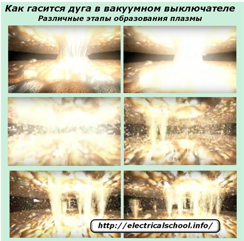
Since the switch operates on alternating current, its direction during each half cycle is reversed.When the sine wave crosses zero, there is no current. Due to this, the arc is abruptly extinguished and broken, and the rejected metal ions cease to separate and in 7-10 microseconds completely settle on the nearest contact surfaces or other parts of the arc extinguishing chamber.
At this point, the dielectric strength of the gap between the power contacts, filled with vacuum, is restored almost immediately, which ensures the final shutdown of the load current. In the next half-cycle of the sine wave, the electric arc can no longer occur.

Thus, to terminate the action of an electric arc in a vacuum environment, when the power contacts are opened, it is enough for the alternating current to change its direction.
Technological characteristics of different models
Vacuum circuit breakers are designed for continuous operation outdoors or in closed structures. External mounting units are made with solid posts made with silicone insulation, and for internal work cast epoxy compounds are used.
The vacuum chambers are manufactured mobile in the factory, optimally set up for installation in a molded housing. Power contacts made of special types of alloyed alloys are already placed inside them. They, thanks to the applied principle of operation and design, provide soft extinguishing of the electric arc, exclude the possibility of overvoltage in the circuit.
A universal electromagnetic actuator is used in all vacuum circuit breaker designs. It keeps the power contacts in the closed or off state due to the energy of powerful magnets.
The switching and fixing of the contact system is carried out by the position of the «magnetic latch», which switches the chain of magnets to reconnect or disconnect the mobile armature. Built-in spring elements allow manual switching by electrical personnel.
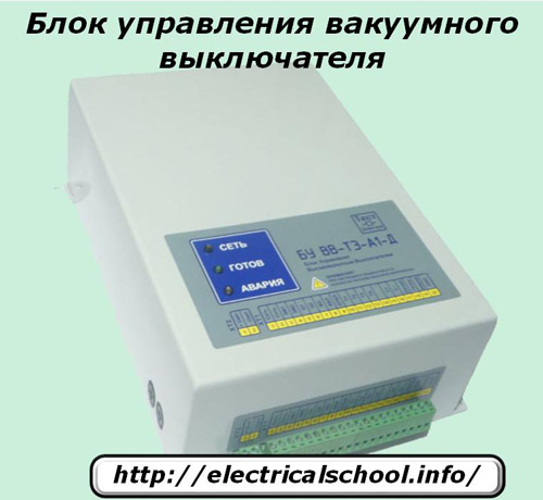
To control the operation of the vacuum interrupter, typical relay circuits or electronic, microprocessor units, which can be located directly in the drive housing or made from remote devices in separate cabinets, blocks or panels.
Advantages and disadvantages of vacuum circuit breakers
Benefits include:
-
relative simplicity of design;
-
reduced electricity consumption for the production of switches;
-
convenience in the repair, which consists in the possibility of block replacement of a broken arc chute;
-
the ability of the switch to operate in any orientation in space;
-
high reliability;
-
increased resistance to switching loads;
-
limited sizes;
-
resistance to fire and explosion;
-
quiet operation when switching;
-
high environmental friendliness, except for atmospheric pollution.
The disadvantages of the design are:
-
relatively low permissible currents of nominal and emergency modes;
-
the occurrence of switching surges during interruptions of low inductive currents;
-
reduced resource of the arc device in terms of elimination of short circuit currents.