Multi-speed electric motors and their use — purpose and characteristics, determination of power at different speeds of rotation
 Multi-speed electric motors — asynchronous motors with several stages of speed, are designed to drive mechanisms that require stepless speed control.
Multi-speed motors are specially designed motors. They have a special stator winding and a normal caged rotor.
Depending on the ratio of poles, the complexity of the circuits and the year of production of multi-speed electric motors, their stators are produced in four versions:
-
independent one-speed coils for two, three, even four speeds;
-
with one or two coils with pole switching, in the first case two-stage, and in the second - four-stage;
-
with the presence of three speeds of rotation of the electric motor, one coil is switched with a pole - two-speed, and the second - single-speed, independent - for any number of poles;
-
with one coil with pole switching for three or four speeds.
Self-winding motors have poor utilization and slot filling due to the presence of a large number of wires and seals, which significantly reduces power in speed steps.
The presence of two pole-switched windings in the stator, and especially one for three or four rotation speeds, improves the filling of the slots and allows a more rational use of the stator core, as a result of which the power of the electric motor increases.
According to the complexity of the circuits, multi-speed electric motors are divided into two parts: with a pole ratio equal to 2/1 and — not equal to 2/1. The first includes electric motors with a speed of 1500/3000 rpm or 2p = 4/2, 750/1500 rpm or 2p = 8/4, 500/1000 rpm or 2p = 12/6, etc., and to the second — 1000 /1500 rpm or 2p = 6/4, 750/1000 rpm or 2p = 8/6, 1000/3000 rpm or 2p = 6/2, 750/3000 rpm or 2p = 8/2, 600/3000 rpm or 2p = 10/2, 375/1500 rpm or 2p = 16/4, etc.
Depending on the choice of the circuit of pole-switched windings, with different number of poles, the electric motor can be either constant power or constant torque.
For motors with a pole-switched winding and constant power, the number of turns in phases at both numbers of poles will be the same or close to each other, which means that their currents and powers will be the same or close. Their torques will be different, depending on the number of revolutions.
In constant-torque electric motors with a smaller number of poles, groups of windings divided into two parts in each phase are connected in parallel in a double delta or double star, as a result of which the number of turns in a phase decreases, and the cross-section of the wire , current and power are doubled.When switching from large to fewer poles in a star / delta arrangement, the number of turns decreases, and the current and power will increase by 1.73 times. This means that at higher power and higher revolutions, as well as at lower power and lower revolutions, the torques will be the same.
The simplest way to get two different numbers of pole pairs is arrangement of the stator of an induction motor with two independent windings… The electrical industry produces such motors with synchronous rotation speeds of 1000/1500 rpm.
However, there are a number of stator winding wire switching schemes where the same winding can produce a different number of poles. A simple and widespread switch of this type is shown in fig. 1, a and b. Stator coils connected in series form two pairs of poles (Fig. 1, a). The same coils connected in two parallel circuits as shown in fig. 1b, form one pair of poles.
The industry produces multi-speed single-winding motors with series-parallel switching and with a speed ratio of 1: 2 with synchronous speeds of rotation 500/1000, 750/1500, 1500/3000 rpm.
The switching method described above is not the only one. In fig. 1, c shows a circuit which forms the same number of poles as the circuit shown in fig. 1, b.
However, the most common in the industry was the first method of series-parallel switching, because with such a switch, fewer wires can be removed from the stator winding and therefore the switch can be simpler.
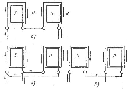
Rice. 1. The principle of switching the poles of an induction motor.
Three-phase windings can be connected to a three-phase network in star or delta. In fig. 2, a and b show a widespread switching, in which the electric motor, in order to obtain a lower speed, is connected with a delta with a series connection of coils, and to obtain a higher speed, a star with a parallel connection of the coils (t .aka double star).
Along with the two-speed, the electrical industry also produces three-speed asynchronous motors... In this case, the stator of the electric motor has two separate windings, one of which provides two speeds through the switching described above. The second winding, usually included in the star, provides the third speed.
If the stator of the electric motor has two independent windings, each of which allows pole switching, it is possible to obtain a four-stage electric motor. In this case, the number of poles is chosen so that the rotation speeds make up the required series. A diagram of such an electric motor is shown in fig. 2, c.
It should be noted that the rotating magnetic field will induce three E in three phases of the idle winding. d. s, of the same size and phase shifted by 120 °. The geometric sum of these electromotive forces, as known from electrical engineering, is zero. However, due to the imprecise sinusoidal phase e. etc. c. mains current, the sum of these d., etc. v. may be zero. In this case, a current arises in a closed non-working coil, which heats this coil.
To prevent this phenomenon, the pole switching circuit is made in such a way that the idle coil is open (Fig. 12, c).Due to the small value of the upper current in some electric motors, sometimes no break is made in the closed loop of the idle winding.
Produced three-speed double-wound motors having synchronous rotation speeds of 1000/1500/3000 and 750/1500/3000 rpm and four-speed motors with 500/750/1000/1500 rpm. Two-speed motors have six, three-speed nine, and four-speed 12 terminals to the pole switch.
It should be noted that there are circuits for two-speed motors, which with one winding make it possible to obtain rotation speeds whose ratio is not equal to 1: 2. Such electric motors provide synchronous rotation speeds of 750/3000, 1000/1500, 1000/3000 rpm
Three and four different numbers of pole pairs can be obtained by using special schemes for a single winding. Such multi-speed electric motors with a single winding are significantly smaller than double-winding motors with the same parameters, which is very important for mechanical engineering.
In addition, single winding electric motors have slightly higher energy indicators and less labor-intensive production. The disadvantage of multi-speed motors with a single winding is the presence of a larger number of wires introduced into the switch.
However, the complexity of the switch is determined not so much by the number of wires brought out as by the number of simultaneous switches. In this regard, schemes have been developed that allow, in the presence of one coil, to obtain three and four speeds with relatively simple switches.
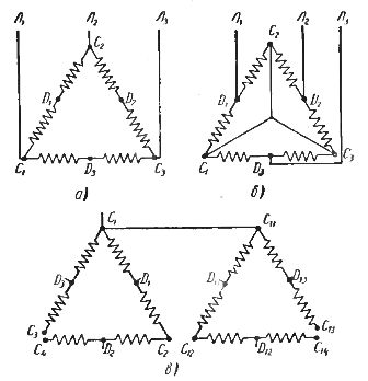
Rice. 2. Schemes for switching the poles of an induction motor.
Such electric motors are produced by mechanical engineering at synchronous speeds of 1000/1500/3000, 750/1500/3000, 150/1000/1500, 750/1000/1500/3000, 500/750/1000/1500 rpm.
The torque of the induction motor can be expressed by the well-known formula

where Ig is the current in the rotor circuit; F is the magnetic flux of the motor; ? 2 is the phase angle between the current vectors and e. etc. v. rotor.
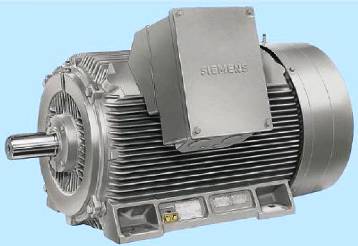
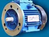
Rice. 3. Three-phase multi-speed squirrel-cage motor.
Consider this formula in relation to speed control of an induction motor.
The highest permissible continuous current in the rotor is determined by the permissible heating and is therefore approximately constant. If the speed regulation is carried out with a constant magnetic flux, then at all motor speeds the maximum long-term permissible torque will also be constant. This speed control is called constant torque control.
Speed regulation by varying the resistance in the rotor circuit is regulation with a constant maximum allowable torque, since the magnetic flux of the machine does not change during regulation.
The maximum permissible useful power of the motor shaft at a lower speed of rotation (and therefore a greater number of poles) is determined by the expression
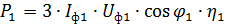
where If1 — phase current, maximum permissible according to heating conditions; Uph1 — phase voltage of the stator with a larger number of poles.
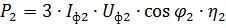
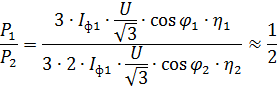
The maximum permissible useful power of the motor shaft at a higher speed of rotation (and a smaller number of poles) Uph2 — phase voltage in this case.
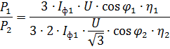
When switching from a delta connection to a star, the phase voltage decreases by a factor of 2.Thus, when moving from circuit a to circuit b (Fig. 2), we get the power ratio
Taking rough

take it
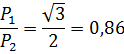
In other words, the power at lower speed is 0.86 of the power at higher rotor speed. Given the relatively small change in maximum continuous power at the two speeds, such regulation is conventionally referred to as constant power regulation.
If, when connecting halves of each phase, you sequentially use a star connection, and then switch to a parallel star connection (Fig. 2, b), then we get
Or
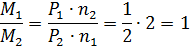
Thus, in this case, there is a constant control of the torque revolutions. In metalworking machine tools, the main motion drives require constant power speed control and the feed drives require constant torque speed control.
The above calculations of the power ratio at the highest and lowest speed are approximate. For example, the possibility of increasing the load at high speeds due to the more intensive cooling of the windings was not taken into account; the assumed equality is also very approximate. So, for the 4A motor we have


As a result, the power ratio of this engine is P1 / P2 = 0.71. Roughly the same ratios apply to other two-speed engines.
New multi-speed single-coil electric motors, depending on the switching scheme, allow speed control with constant power and constant torque.
The small number of control stages that can be obtained with pole-changing induction motors usually allows such motors to be used on machine tools only with specially designed gearboxes.
See also: Advantages of using multi-speed motors