Lightning protection device
 Lightning protection devices (lightning rods) consist of lightning rods mounted on poles or directly on a building, down conductors and grounding electrodes.
Lightning rods
Lightning rods directly perceive a direct lightning strike. By design, they can be rod-shaped (fixed on supports) or cable (suspended over the protected object).
A grid welded from steel wire with a diameter of 6-8 mm, with cells of 6×6 mm, laid on the roof or under a layer of non-combustible insulation can also be used as a lightning rod.
Lightning arresters are made of steel of any class and profiles with a cross-section of at least 100 mm2 (the smallest diameter is 12 mm). The minimum length of the air terminal is 200 mm. The most rational length is 1-1.5 m. Typical structures of lightning rods are shown in fig. 1.
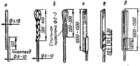
Rice. 1. Projects of lightning rods: a — from round steel; b — made of steel wire; e — from a steel pipe; g — from strip steel; d-angle steel
Lightning rods are galvanized or painted to protect against corrosion. No copper plating or additionally gold and silver plating is required on the tip of the lightning rod.
Contact network lightning rods are made of galvanized multi-wire steel wire with a cross-section of at least 35 mm2 (diameter about 7 mm), stretched over an elongated protected object. It is necessary to connect lightning rods with down conductors by welding.
supports
Supports for free-standing lightning rods can be made of steel, antiseptic wood and reinforced concrete. It is allowed to use tree trunks growing at a distance of 5-10 m from the protected site as supports for lightning rods (Fig. 2).
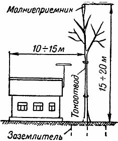
Rice. 2. Lightning protection of a building using a lightning rod mounted on a tree
For objects of II and III category of lightning protection with III, IV and V degrees of fire resistance, trees growing at a distance of less than 5 m from buildings or structures can be used as supports for lightning rods, if one of the following conditions is met is fulfilled:
1. Along the wall of the protected building against the tree, along the entire height of the building, a wire is laid down, the lower end of which is buried in the ground and connected to the grounding electrode;
2. from a lightning rod installed on a tree, the wire is thrown down to another tree located at a distance of more than 5 m from the protected building. The descending wire descends this tree and is connected to the ground electrode.
For trees equipped and not equipped with lightning rods, the branches must be cut from the side of the house at a distance of at least 3 m from the building.
Lower wires
Down conductors are conductors connecting rods or lightning rods to a catenary or roof air-break network with a grounding conductor.
It is allowed to use metal structures as down conductors: columns, longitudinal reinforcement of reinforced concrete columns, fire escapes, pipes, etc.
Down conductors should be located away from building entrances so that people cannot touch them.
They should be galvanized or painted to protect against corrosion. It is recommended to place them along the protected building along the shortest path to the electrode grounding system. All joints of down conductors and their connections to earth conductors must be welded.
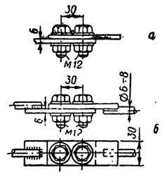
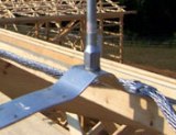
Rice. 3. The construction of the connector between the lower wire and the grounding electrode: a — the lower wire made of steel tape; b — round steel wire down
The value of the impulse resistance of the grounding electrode can be determined from the value of the resistance for the power frequency current by the formula:

where α is the impulse coefficient, depending on the magnitude of the lightning current, the length of the horizontal conductors of the earth electrode system and the specific resistance of the soil; R ~ — power frequency current propagation resistance.
The type of earthing switch is selected based on the specific resistance of the soil and the required resistance value,
If in the vicinity of the protected structure (at a distance of 25 — 35 m) there is a protective earthing intended for electrical installations, for example, the earthing of a substation, then it must also be used for the purposes lightning protection of buildings… In most cases, the resistance of the protective earth is less than that required for lightning protection.
An example. It is necessary to choose a grounding device for the lightning rod protecting the residential building. The soil is clayey with a normal moisture content.
According to the data on soil resistance, we find for clay soil ρ = 40— 150 Ohm • m. We take the average value of 100 Ohm • m.
According to the reference table, we find that the protected object belongs to the III category of lightning protection, and therefore the impulse resistance of the grounding electrode should be no more than 20 Ohm:
Rp <20 ohms
We choose for p = 100 Ohm • m the resistance of the grounding electrode, close to 20 Ohm.
The closest and most convenient from the point of view of installation are grounding devices according to sketch 2; two-ground earthing switch made of rods with a diameter of 10-16 mm or angles 40x40x4 mm, 2.5 m long at a distance of 3 m from each other, connected by a steel strip of dimensions 40x4 mm at a depth of 0.8 m (resistance R (2)~ = 15 — 14 Ohm), or according to sketch 7: a horizontal earthing switch made of a strip 40×4 mm 5-10 m long at a depth of 0.8 m with feed to the middle (resistance R (7) ~ = 12-19 ohms). For the first option, you need to find the impulse factor from the lookup tables.
For ρ = 100 ohm • m α = 0.7
For grounding according to sketch 2: R(2) n = α • R(2)~ = 10.5 ohms.
For the earthing switch according to sketch 7, the pulse coefficient is not taken into account, therefore: R(7) n = R(7)~ = 19 ohms at 5 m length (or 12 ohms at 10 m length).
In both cases, the necessary grounding resistance is provided. We accept option according to sketch 2 as less labor intensive and gives some margin of safety. If, according to local conditions, there are difficulties in driving a corner or screwing electrodes with round rods, it is perfectly acceptable to ground the lightning rod according to sketch 7 (tape length 5-10 m).