Valve motor
DC machines, as a rule, have higher technical and economic indicators (linearity of characteristics, high efficiency, small dimensions, etc.) than alternating current machines. A significant disadvantage is the presence of a brush apparatus, which reduces reliability, increases the moment of inertia, creates radio interference, explosion hazard, etc. Therefore, naturally, the task of creating a contactless (brushless) DC motor.
The solution to this problem became possible with the advent of semiconductor devices. In a contactless DC motor, called a constant valve current motor, the brush set is replaced by a semiconductor switch, the armature is stationary, the rotor is permanent magnet.
The principle of operation of the valve engine
 The valve motor is understood as a variable electric drive system consisting of an alternating current electric motor structurally similar to a synchronous machine, a valve converter and control devices that provide commutation of the motor winding circuits depending on the position of the motor rotor.In this sense, a valve motor is similar to a DC motor in which, by means of a commutation switch, that turn of the armature winding, which is located below the field poles, is connected.
A DC motor is a complex electromechanical device that combines the simplest electrical machine and an electronic control system.
Direct current motors have serious disadvantages, mainly due to the presence of a brush collector:
1. Insufficient reliability of the collector apparatus, the need for its periodic maintenance.
2. Limited values of armature voltage and, accordingly, the power of DC motors, which limits their use for high-speed, high-power drives.
3. Limited overload capacity of DC motors, limiting the rate of change of armature current, which is essential for highly dynamic electric drives.
In a valve engine, these disadvantages do not manifest themselves, since here the brush-collector switch is replaced by a non-contact switch made on thyristors (for high-power drives) or transistors (for drives with a power of up to 200 kW). Based on this, a valve motor that is structurally based on a synchronous machine is often called a contactless DC motor.
In terms of controllability, a brushless motor is also similar to a DC motor—its speed is adjusted by varying the magnitude of the DC voltage applied. Due to their good regulating qualities, valve motors are widely used to drive various robots, metal cutting machines, industrial machines and mechanisms.
Permanent magnet transistor commutator with electric drive
The valve motor of this type is made on the basis of a three-phase synchronous machine with permanent magnets on the rotor. Three-phase stator windings are supplied with direct current supplied in series to two series-connected phase windings. The switching of the windings is carried out by a transistor switch made according to a three-phase bridge circuit. The transistor switches are opened and closed depending on the position of the motor rotor. The valve motor diagram is shown in fig.
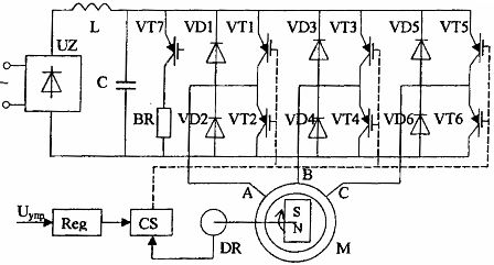
Fig. 1. Diagram of a valve motor with a transistor switch
The torque created by the motor is determined by the interaction of two threads:
• the stator created by the current in the stator windings,
• rotor created from high-energy permanent magnets (based on samarium-cobalt alloys and others).
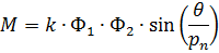
where: θ is the solid angle between the stator and rotor flux vectors; pn is the number of pole pairs.
The stator magnetic flux tends to rotate the permanent magnet rotor so that the rotor flux matches in direction with the stator flux (don't forget the magnetic needle, compass).
The largest moment created on the rotor shaft will be at an angle between the flux vectors equal to π / 2 and will decrease to zero as the flux flows approach. This dependence is shown in Fig. 2.
Let us consider the spatial diagram of the flux vectors corresponding to the motor mode (with the number of pole pairs pn = 1). Suppose that at the moment transistors VT3 and VT2 are turned on (see the diagram in Fig. 1). Then the current flows through the winding of phase B and in the opposite direction through the winding of phase A. The resulting vector ppm. the stator will occupy position F3 in space (see figure 3).
If the rotor is now in the position shown in fig. 4, then the motor will develop according to 1 the maximum torque at which the rotor will turn clockwise. As the angle θ decreases, the torque will decrease. When the rotor is rotated 30 °, it is necessary according to the graph in fig. 2. switch the current in the motor phases so that the resulting ppm vector stator is in position F4 (see Fig. 3). To do this, turn off the transistor VT3 and turn on the transistor VT5.
Phase switching is carried out by a transistor switch VT1-VT6 controlled by the rotor position sensor DR; in this case, the angle θ is maintained within 90 ° ± 30 °, which corresponds to the maximum torque value with the smallest ripples. At ρn = 1, six switches must be made per one revolution of the rotor, therefore ppm. the stator will make a full revolution (see Fig. 3). When the number of pole pairs is greater than unity, the rotation of the ppm vector the stator and therefore the rotor will be 360/ pn degrees.
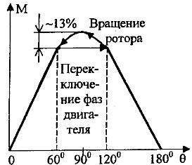
Fig. 2. Dependence of the motor torque on the angle between the stator and rotor flux vectors (at pn = 1)

Fig. 3. Spatial diagram of the ppm stator when switching the phases of the valve motor
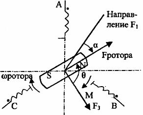
Fig. 4. Spatial diagram in motor mode
Adjusting the torque value is done by changing the ppm value. stator, i.e. change in the average value of the current in the stator windings

where: R1 is the stator winding resistance.
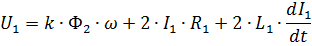
Since the motor flux is constant, the emf induced in two series-connected stator windings will be proportional to the rotor speed.The electrical equilibrium equation for the stator circuits will be
When the switches are off, the current in the stator windings does not disappear immediately, but is closed through the reverse diodes and the filter capacitor C.
Therefore, by adjusting the motor supply voltage U1, it is possible to adjust the magnitude of the stator current and the motor torque

It is easy to see that the obtained expressions are similar to analogous expressions for a DC motor, with the result that the mechanical characteristics of a valve motor in this circuit are similar to the characteristics of a DC motor with independent excitation at Φ = const .
A change is made in the supply voltage of the brushless motor in the circuit under consideration by the pulse width adjustment method… By changing the duty cycle of the pulses of transistors VT1-VT6 during the periods of their inclusion, it is possible to adjust the average value of the voltage supplied to the stator windings of the motor.
To apply the stop mode, the transistor switch operation algorithm must be changed in such a way that the stator ppm vector lags the rotor flux vector. Then the motor torque will become negative. Since an uncontrolled rectifier is installed at the input of the converter, regeneration of braking energy in this circuit is impossible.
During shutdown, the capacitor of the filter C is recharged. The voltage limitation on the capacitors is carried out by connecting the discharge resistance through the transistor VT7. In this way, the braking energy is dissipated in the load resistance.