Thyristor control of an induction motor in a cage
 To control an asynchronous motor, thyristors can be used in combination with relay-contactor devices. Thyristors are used as power elements and are included in the stator circuit, relay-contactor devices are included in the control circuit.
Using thyristors as power switches, it is possible to apply a voltage from zero to the nominal value to the stator at start-up, to limit motor currents and torques, to perform effective braking or stepping action. Such a scheme is shown in fig. 1.
The power supply part of the circuit consists of a group of thyristors VS1 ... VS4, connected antiparallel to phases A and B. A short circuit thyristor VS5 is connected between phases A and B. The circuit consists of a power supply circuit (Fig. 1, a), a control circuit ( Fig. 1, b) and thyristor control unit — BU (Fig. 1, c).
To start the engine, the QF switch is turned on, the «Start» button SB1 is pressed, as a result of which the contactors KM1 and KM2 are turned on.Thyristor control electrodes VS1 … VS4 are supplied with pulses shifted by 60 ° relative to the supply voltage. A lower voltage is applied to the motor stator, resulting in a reduction in starting current and starting torque.
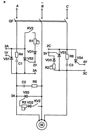
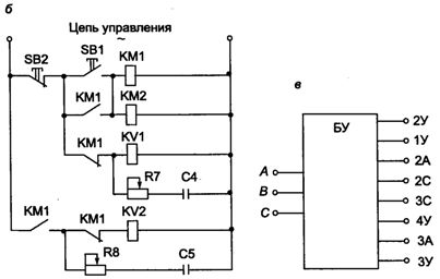
Rice. 1. Thyristor control of a squirrel-cage induction motor
The opening contact KM1 breaks the relay KV1 with a time delay, which is determined by the resistor R7 and the capacitor C4. The open contacts of the KV1 relay connect the corresponding resistors in the control unit and the full line voltage is supplied to the stator.
To stop, press the «Stop» button SB2. The control circuit loses power, thyristors VS1 … VS4 are turned off. This leads to the fact that during the shutdown period, the relay KV2 turns on due to the energy stored by the capacitor C5 and, through its contacts, turns on the thyristors VS2 and VS5. A direct current flows through phases A and B of the stator, which is regulated by resistors R1 and R3. Effective dynamic braking.