High frequency electric motors
 When grinding small holes, very high grinding spindle speeds are required to achieve adequate cutting speeds. So, when grinding holes with a diameter of 5 mm with a circle with a diameter of 3 mm at a speed of only 30 m / s, the spindle must have a rotation speed of 200,000 rpm.
The application to increase the speed of the belt drive is limited by the maximum allowable revolutions of the belt. The speed of rotation of spindles driven by belts usually does not exceed 10,000 revolutions per minute, and the belts slip, quickly fail (after 150-300 hours) and create vibrations during operation.
High-speed pneumatic wheels are also not always suitable due to the very significant softness of their mechanical characteristics.
The problem of creating high-speed spindles is of particular importance for the production of ball bearings, where high-quality internal and groove grinding is required. In this regard, numerous models of so-called electrospindles with rotation speeds of 12,000-50,000 rpm and more are used in the machine tool and ball bearing industry.
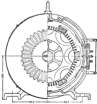
The electric spindle (Fig. 1) is a three-nose grinding spindle with a built-in high-frequency squirrel-cage motor. The motor rotor is located between two spurs at the end of the spindle opposite the grinding wheel.
Constructions with two or four supports are less often used. In the latter case, the motor shaft is connected to the spindle using a coupling.
The stator of the spindle motor is assembled from electrical steel sheet. It has a bipolar coil on it. The rotor of the motor at rotation speeds of up to 30-50 thousand revolutions per minute is also dialed from sheet metal and equipped with a conventional short-circuit winding. They tend to reduce the diameter of the rotor as much as possible.
At speeds above 50,000 rpm, due to significant losses, the stator is equipped with a casing with cooling of flowing water. The rotors of engines designed to operate at such speeds are made in the form of a solid steel cylinder.
The choice of bearing type is of particular importance for the operation of electrospindles. Spherical bearings with increased accuracy are used at rotational speeds up to -50,000 rpm. Such bearings must have a maximum clearance of no more than 30 microns, which is achieved by proper filling. Bearings operate with a preload created using calibrated springs. Great care must be taken when calibrating ball bearing preload springs and selecting their fit.
At rotational speeds above 50,000 revolutions per minute, the journal bearings work satisfactorily when they are intensively cooled by working oil supplied by a special pump. Sometimes the lubricant is supplied in a sprayed state.
High-frequency 100,000 rpm electrospindles are also built on aerodynamic bearings (air-lubricated bearings).
The production of high-frequency electric motors requires very precise manufacturing of individual parts, dynamic balancing of the rotor, precise assembly and ensuring strict uniformity of the gap between the stator and the rotor.
In connection with the above, the production of electric spindles is carried out according to special technical conditions.
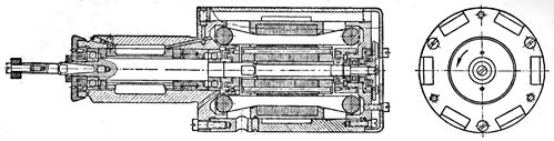
Fig. 1. High frequency electric grinding spindle.
The efficiency of high-frequency motors is relatively small. This is due to the presence of increased steel losses and bearing friction losses.
The dimensions and weight of high-frequency electric motors are relatively small.
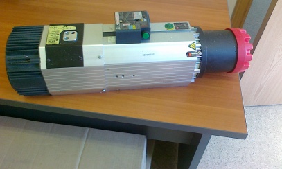
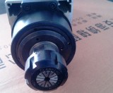
Rice. 2. Modern high frequency electric spindle
The use of electric spindles instead of belt drives in the production of ball bearings increases the labor productivity of internal grinding machines by at least 15-20% and sharply reduces rejections in taper, ovality and surface cleanliness. The durability of grinding spindles is increased by 5-10 times or more.
The use of high-speed spindles for drilling holes with a diameter of less than 1 mm is also of great interest.
The frequency of the current supplying the high-frequency electric motor is selected depending on the required rotation speed n of the electric motor according to the formula
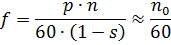
since p = 1.
So, at rotation speeds of electric spindles of 12,000 and 120,000 rpm, frequencies of 200 and 2000 Hz are required, respectively.
Special high-frequency generators were previously used to power high-frequency motors.Now, for these purposes, static frequency converters are used on high-speed field-effect transistors.
In fig. 3 shows a three-phase synchronous induction generator of domestic production (type GIS-1). As can be seen from the drawing, there are wide and narrow grooves on the stator of such a generator. The field winding, whose coils are located in the wide slots of the stator, is supplied with direct current. The magnetic field of these windings is enclosed through the stator teeth and rotor projections as shown in fig. 3 with dotted line.
Rice. 3. Induction current generator with increased frequency.
When the rotor rotates, the magnetic field moving along the rotor protrusions crosses the turns of the alternating current winding located in the narrow slots of the stator and induces an alternating e. etc. c. The frequency of this e. etc. c. depends on the speed of rotation and the number of rotor ears. The electromotive forces induced by the same flux in the field-wound windings cancel each other due to the impending activation of the coils.
The excitation coil is fed through a selenium rectifier connected to the AC mains. Both the stator and the rotor have magnetic cores made of sheet steel.
Generators with the described design are produced with a nominal power of 1.5; 3 and 6 kW and at frequencies of 400, 600, 800 and 1200 Hz. The nominal speed of rotation of synchronous generators is 3000 rpm.