External characteristics of the EMF source
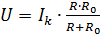
The external characteristic reflects the dependence of the source terminal voltage on the magnitude of the load — the source current given by the load. The source terminal voltage is less than the EMF by the amount of voltage drop internal resistance of the source (1):

This equation corresponds to the external characteristic of the EMF source (Fig. 1). built on two points:
1) at I = 0 E = U;
2) at U = 0 E = R0I.
Obviously, the higher the voltage at the terminals of the EMF source, the lower its internal resistance.
In an ideal EMF source, R0 = 0, U = E (the voltage does not depend on the magnitude of the load). However, when analyzing and calculating a circuit, it is not always convenient to represent the source of electrical energy as a source of EMF. If the internal resistance of the source significantly exceeds the external resistance of the circuit, which, for example, occurs in electronics, then we get that the current in the circuit I = U / (R + R0) and at R0 >> R practically does not depend on the load resistance. In this case, the energy source is presented as a current source.
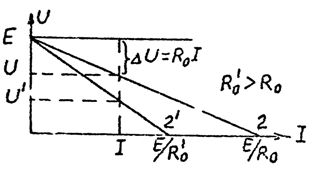
Fig. 1.
We divide equation (1) by R0 (2):

Equation (2) corresponds to the equivalent circuit shown in Fig. 2. Here Ib = U / R0 and Ik = E / R0, I = Ik — Ib then (3)
For an ideal current source, Rc = ∞. The current-voltage characteristics of real and ideal current sources are shown in Fig. 3.
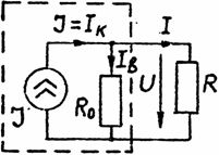
Rice. 2
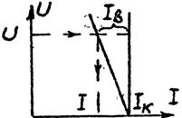
Rice. 3
When there is no clear distinction between the values of R and R0, either an EMF source or a current source can be used as the calculated equivalent of the power source. In the latter case, expression (3) is used to determine the voltage drop.
Source operating modes
The source can work in the following modes:
1. Rated mode is the mode of operation for which the source is designed by the manufacturer. For this mode, the nominal current Inom and the nominal voltage Unom or the power Pnom are indicated in the passport of the source.
2. Idle mode. In this mode, the external circuit is disconnected from the source, the source current is I = 0, and therefore the source terminal voltage is the open circuit voltage Uxx = E — see equation (1).
3. Short circuit mode. The resistance of the circuit external to the source is zero. The source current is limited only by its internal resistance. From equation (1) at U = 0 we obtain I = Ikz = U / R0. To reduce energy losses in the EMF source, R0 should be as small as possible, and in an ideal source R0 = 0. Given this, Ikz >> Inom and is unacceptable for the source.
4. Contract mode — this is a mode in which the maximum power is transmitted from the source to the user. You can determine this power through the source parameters. So, the power transferred to the load, P = I2R. P = Pmax at R = R0.Then the maximum power delivered to the user is Pmax = E2 / 4R0. The efficiency of the source in compliance mode does not exceed 50%. which excludes its use in industrial electrical engineering. The corresponding mode is used in low-current circuits of electronic devices.