Selection of equipment for starting synchronous electric motors
 One of the reasons that previously limited the use of synchronous motors, was the complexity of the schemes and the methods of launching them. Currently, operational experience and experimental work have proven the possibility of significantly simplifying the methods of starting synchronous electric motors.
Asynchronous start of synchronous electric motors in the majority of cases can be done from the full voltage of the network, and the exciter in light starting conditions happens directly to the rotor winding. In this case, the control circuits are close in their simplicity to the control circuits of asynchronous electric motors with a squirrel-cage rotor.
For those cases where, according to the conditions of the power network, the direct start of the electric motor is impossible, schemes are used for starting from under voltage through a reactor or autotransformer (for high-voltage electric motors) and through active resistance in the stator (for low-voltage electric motors).
By the nature of the power supply to the motor winding, the following starting methods are used:
1. black connection of the exciter to the rotor winding,
2. connecting the exciter to the rotor winding through resistance, which at the end of the run is overcome by the excitation contactor.
Starting by the first method is used in light conditions when the moment of resistance of the mechanism during starting does not exceed 0.4 of the nominal (engine-generators, synchronous compensators, reciprocating and centrifugal compressors without starting a load, pumps start with a closed valve and etc.).). The same switching is possible at high resistance torques if confirmed by the motor manufacturer.
In more severe starting conditions (ball mills, mixing units, fans and compressors started under load, pumps with an open valve, etc.), it is carried out by the second method. The resistance value is taken equal to 6-10 times the resistance of the rotor winding. With this resistance, the energy of the motor's magnetic field is extinguished during stops and during protection operation.
For large critical motors that are protected from internal damage and used for long stroke drives (eg motor generators), a circuit with field suppression by discharge resistance can be used.
The excitation contactor, where used, is made with a latch, which makes the operation of the motor after it has been started independent of the control circuits and of the operability of the contactor coil.
Activation of the field contactor, as well as tripping of the circuit breaker or undervoltage starter, is done by the current relay as a function of the stator inrush current, which falls when the synchronous speed is reached (approximately equal to 95% of the synchronous speed) .
At the end of the start, the coil of the current relay is removed from the circuit to prevent the relay from repeatedly turning on when the load is disconnected. The impulse from the current relay is fed through two blocking time relay, which create an additional time delay before applying the excitation.
In substations with alternating current circuits, the latching relays are powered by solid-state rectifiers.
When the supply voltage drops to 0.75-0.8 of the nominal value, the motor excitation is forced to the limit value, which is automatically removed when the voltage rises to 0.88-0.94 of the nominal value.
Forced excitation increases the stability of the parallel operation of the power system in emergency modes, the voltage level at the consumer buses and the stability of the drive itself.
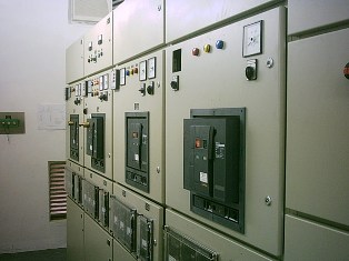
The following types of protection are commonly used for synchronous motors:
1. at low voltage:
a. overcurrent protection installation automatic device with electromagnetic release that protects against short circuit and with thermal release that protects the motor from overload and operation in asynchronous mode,
b. zero protection, running immediately or with a time delay of up to 10 seconds,
2. at high voltage:
a.maximum current protection, protection against overload and against the operation of the motor in asynchronous mode, provided by a relay with a limited dependent characteristic of the IT type, with a shock nature of the load, when the settings of the current relays are increased, a field interruption relay is installed, also called a zero current relay (RNT) that can act on a signal or switch off the motor,
b. longitudinal differential protection using relay ET521, for electric motors with a power of 2000 kW and more,
° C. earth fault protection for earth fault currents above 10 A, provided by ETD521 current relays responding to zero sequence currents,
e. zero protection — individual or group.
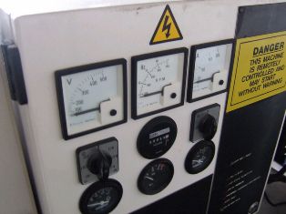
For energy measurement and reading, an ammeter is installed in the stator circuit, a double-ended ammeter in the excitation circuit, and counters for active and reactive energy... For engines with a power of 1000 kW and more, a wattmeter with a switch for measuring active and reactive power is additionally installed.
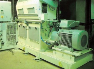
Control stations are used to control synchronous motors.
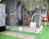
Synchronous motors are usually made with an exciter on the same shaft. In the case of a stand-alone exciter, an additional box with a locking contactor is used to control the exciter.