DC generators
The principle of operation of the DC generator
 The generator is based on the use of the law of electromagnetic induction, according to which in a conductor moving in a magnetic field and crossing the magnetic flux, is induced by ef.
One of the main parts of a DC machine is the magnetic circuit through which the magnetic flux is closed. The magnetic circuit of a DC machine (Fig. 1) consists of a stationary part — stator 1 and a rotating part — rotor 4. The stator is a steel case to which other parts of the machine are attached, including magnetic poles 2. On the magnetic poles 3, an exciting coil is placed, powered by direct current and creating the main magnetic flux Ф0.
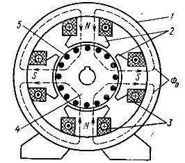
Rice. 1. Magnetic circuit of a four-pole DC machine
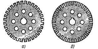
Rice. 2. Sheets from which the magnetic circuit of the rotor is assembled: a — with open channels, b — with semi-closed channels
The rotor of the machine is assembled from stamped steel sheets with circumferential grooves and holes for the shaft and ventilation (Fig. 2). In the channels (5 in Fig. 1) of the rotor is laid the working winding of the DC machine, that is, the winding in which em is induced by the main magnetic flux. etc. withThis winding is called an armature winding (hence the rotor of a DC machine is usually called an armature).
The meaning of e. etc. c. The DC generator can be switched but its polarity remains constant. The working principle of the DC generator is shown in fig. 3.
The poles of a permanent magnet create a magnetic flux. Imagine that the armature winding consists of one turn, the ends of which are attached to different half-rings, isolated from each other. These half rings form a collector, which rotates with the turn of the armature winding. At the same time, the stationary brushes slide along the collector.
When the coil rotates in a magnetic field, an emf is induced in it

where B is the magnetic induction, l is the length of the wire, v is its linear velocity.
When the plane of the coil coincides with the plane of the center line of the poles (the coil is located vertically), the wires cross the maximum magnetic flux and the maximum value of e is induced in them. etc. c. When the contour is horizontal, e.g. etc. v. in the wires is zero.
The direction of e., etc. p in the conductor is determined by the right-hand rule (in Fig. 3 is shown by arrows). When during the rotation of the coil the wire passes under the other pole, the direction of e. etc. v. he is converted. But since the collector rotates with the coil and the brushes are stationary, then a wire located below the north pole is always connected to the upper brush, e.g. etc. v. which is directed away from the brush. As a result, the polarity of the brushes remains unchanged and therefore remains unchanged in the e direction. etc. on brushes — egSCH (Fig. 4).
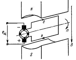
Rice. 3. The simplest DC generator
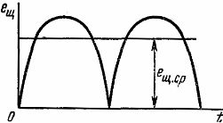
Rice. 4. Change in time of electromotive force.the simplest DC generator
Although e. etc. c. The simplest direct current generator is constant in direction, its value changes, rotating twice the maximum and twice the zero values in one revolution. A DC with such a large ripple is unsuitable for most DC receivers and in the strict sense of the word cannot be called constant.
To reduce ripple, the armature winding of the DC generator is made of a large number of turns (coils), and the collector is made of a large number of collector plates isolated from each other.
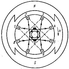
Let's consider the process of smoothing waves, using the example of a round armature winding (Fig. 5), consisting of four windings (1, 2, 3, 4), two turns in each. The armature rotates clockwise with a frequency n and e is induced in the armature winding wires located on the outside of the armature. etc. (the direction is indicated by arrows).
The armature winding is a closed circuit consisting of series-connected turns. But in terms of brushes, the armature winding is two parallel branches. In fig. 5, and one parallel branch consists of coil 2, the second consists of coil 4 (in coils 1 and 3, EMF is not induced and they are connected at both ends to one brush). In fig. 5b, the anchor is shown in the position it takes after 1/8 of a turn. In this position, one parallel armature winding consists of series-connected coils 1 and 2, and the second of series-connected coils 3 and 4.
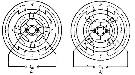
Rice. 5. Scheme of the simplest DC generator with a ring armature
Each coil, when the armature rotates with respect to the brushes, has a constant polarity. Change of address, etc. c. windings in time with the rotation of the armature is shown in fig. 6, a. D. d.C. on brushes is equal to e. etc. v. each parallel branch of the armature winding. Fig. 5 shows that e. etc. c. parallel branch is equal to or e. etc. c. one coil or the quantity e. etc. c. two adjacent windings:

As a result of this pulsation of e. etc. c. the armature windings are significantly reduced (Fig. 6, b). By increasing the number of turns and collector plates, an almost constant radiation can be obtained. etc. v. armature windings.
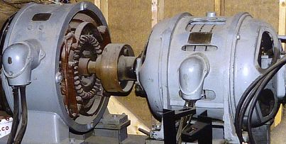
DC Generator Design
In the process of technical progress in electrical engineering, the design of DC machines changes, although the basic details remain the same.
Consider a device of one of the types of DC machines produced by industry. As stated, the main parts of the machine are the stator and the armature. Stator 6 (Fig. 7), made in the form of a steel cylinder, serves both to fasten other parts and to protect against mechanical damage and is a stationary part of the magnetic circuit.
Magnetic poles 4 are attached to the stator, which can be permanent magnets (for low power machines) or electromagnets. In the latter case, an exciting coil 5 is placed on the poles, supplied with direct current and creating a stationary magnetic flux relative to the stator.
With a large number of poles, their windings are connected in parallel or in series, but so that the north and south poles alternate (see Fig. 1). Additional poles with their own windings are located between the main poles. End shields 7 are attached to the stator (Fig. 7).
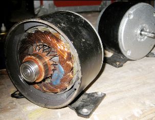
The armature 3 of the DC machine is assembled from sheet steel (see Fig. 2) to reduce power losses from eddy currents. The sheets are insulated from each other.The armature is a movable (rotating) part of the machine's magnetic circuit. The reinforcement or working coil 9 is placed in the ducts of the reinforcement.
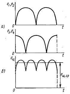
Rice. 6. Amendment in the ERC time from the windings and the winding of the ring fitting
Machines are currently manufactured with an armature and drum type of winding. The pre -examined winding of the annular fittings has the disadvantage that E. etc. c. is induced only in conductors located on the outer surface of the armature. Therefore, only half of the wires are active. In the coil of the drum fitting, all the wires are active, that is, to create the same E. as with a ring-armature machine nearly half the conductive material is required.
The conductors of the armature winding, located in the grooves, are interconnected by the front parts of the turns. Each slot usually contains several wires. The conductors of one slot are connected to the conductors of the other slot to form a series connection called a coil or section. The sections are connected in series and form a closed circuit. The bonding sequence should be such that e. etc. v. in wires included in one parallel branch had the same direction.
In fig. 8 shows the simplest drum armature winding of a two-pole machine. The solid lines show the connection of the sections to each other on the collector side, and the dashed lines show the end connections of the wires on the opposite side. Strips are made from the connection points of the sections to the collector plates. The direction of e., etc. p. in the wires of the coil is shown in the figure: «+» — direction from the reader, «•» — direction to the reader.
The winding of such an armature also has two parallel branches: the first formed by the wires of the slots 1, 6, 3, 8, the second — by the wires of the slots 4, 7, 2, 5. When the armature rotates, the combination of the slots whose wires form a parallel branch, changes all the time, but always the parallel branch is formed by the wires of the four channels, which occupy a constant position in space.
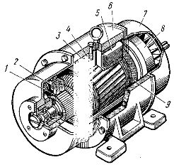
Rice. 7. The arrangement of the drum-type armature DC machine
Rice. 8. The simplest winding
The machines produced by the factories have tens or hundreds of grooves along the circumference of the armature of the drum and the number of collector plates equal to the number of sections of the armature winding.
Collector 1 (see Fig. 7) consists of copper plates, isolated from each other, which are connected to the connection points of the sections of the armature winding and serves to convert the variable e. etc. v. in the wires of the armature winding in constant e. etc. c. on the brushes 2 of the generator or conversion of direct current supplied to the brushes of the motor from the network into alternating current in the wires of the armature winding of the motor. The collector rotates with the armature.
When the armature rotates, fixed brushes 2 slide along the collector. The brushes are graphite and copper-graphite. They are mounted in brush holders that can be rotated at a certain angle. An impeller 8 for ventilation is connected to the anchor.
Classification and parameters of DC generators
The classification of DC generators is based on the type of power source of the excitation coil. Distinguish:
1.self-excited generators, the excitation coil of which is powered by an external source (battery or other direct current source). In low-power generators (tens of watts), the main magnetic flux can be created by permanent magnets,
2. Self-excited generators, the excitation coil of which is powered by the generator itself. According to the connection scheme of the armature and excitation windings in relation to the external circuit, there are: parallel excitation generators, in which the excitation winding is connected in parallel with the armature winding (shunt generators), series excitation generators, in which these windings are connected in series (series generators), generators with mixed excitation, in which one exciting winding is connected in parallel with the armature winding, and the second in series (combined generators).
The rated mode of the DC generator is determined by the rated power - the power that the generator gives to the receiver, the rated voltage at the terminals of the armature winding, the rated current of the armature, the excitation current, the rated frequency of rotation of the armature. These values are usually indicated in the passport of the generator.