Sources and networks of alternating and rectified operating current
 To reduce the cost of electrical equipment and simplify its operation at substations up to 110 kV, they use working alternating and rectified current. As sources of operating alternating current, conventional or special low-power auxiliary transformers, as well as current and voltage measuring transformers.
The control and signaling circuits can be powered from the auxiliary network of the substation or from special low-power power transformers connected to the 6 or 10 kV busbars on the supply side (next to the switches).
Sources of alternating and rectified current unlike batteries, they are not autonomous, since their operation is possible only with the presence of voltage in the network. Therefore, special requirements are imposed on the power supply circuits aimed at increasing the reliability of their operation: the working circuits must be powered by at least two transformers, the voltage in the secondary circuits must be stabilized, the secondary circuits must be separated from the circuits. n.
Power must be provided to the most critical electrical receivers with operating current automatic backup power supply (ATS) devices.
In fig. 1 shows the supply circuit of the AC operating circuits of two transformers TSH1 and TSH2. The most critical electrical receivers are allocated to special SHOP busbars, which are powered by an automatic backup power switch (ATS).
Control buses SHU and signaling SHS are powered from the buses SHOP through stabilizers CT1, CT2, so that voltage fluctuations in the circuits have less impact on the operation of the control and signaling circuits. The electromagnets for turning on the oil switches are powered by the rectifiers VU1 and VU2, which are connected to different sections of the circuit board.
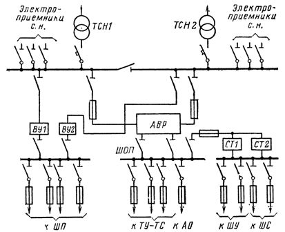
Rice. 1. Power supply circuit for working circuits of alternating current: TCH1, TСН2 — transformers p.n., AVR — automatic transfer switch, ST1, ST2 — voltage stabilizers, VU1, VU2 — rectifiers, SHU, SHP, SHS — control , power and signal busbars, AO — emergency lighting, TU — TS — remote control and remote signaling, SHOP — tires for responsible consumers
On the rectified voltage side, VU1 and VU2 operate on common buses.If the installation uses switches with spring drives (PP-67, etc.) operating on alternating current, the circuit changes accordingly: the rectifiers are turned off, the switching electromagnets are powered from the ShU busbars, since the switching electromagnets of such drives do not require high power, as the engagement is done by the pre-coiled drive springs.
Along with general-purpose power transformers, special transformers are used to power secondary circuits. For example, TM-2/10 transformers with a power of 2 kVA, a nominal voltage of 6 or 10 kV on the upper side and 230 V on the lower side are used to supply control circuits of substations.
Measuring current transformers (CT) and voltage (VT) are also used as sources of alternating current and to supply alternating current to the rectifiers in rectified operating current systems.
Several devices and relays can be connected in series to the secondary winding of the TT.
The error of CTs and the value of their secondary load are closely related to each other. As the load increases, the error of the CT increases, therefore the secondary load for the CT should not exceed the permissible value at which the corresponding accuracy class is ensured.
The peculiarity of the operation of CTs feeding the working current circuits through the rectifiers is that their load in this mode is much greater than when powering only the protective and measuring circuits. Therefore, CT cores operate in saturation mode, which degrades the thermal mode of operation.
The CT error check for a non-linear load is carried out, as well as for a linear one, according to the curves of the limit multiplicity of the secondary current. The difference lies in the fact that the curve of the dependence of the secondary current on the load must lie below the curve of the permissible multiplicity (1) in the entire range of variation of the current from zero to the calculated multiplicity (Fig. 2).
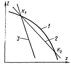
Rice. 2. Curves of the allowable error of the CT with a non-linear load: 1 — the curve of the limit multiplicity, 2, 3 — the characteristics of the non-linear load, K1, K2 — the saturation coefficient of the current transformers
The curves shown in this figure show that the load corresponding to curve 2 at a multiplicity K2 exceeds the allowable, and the corresponding curve 3 does not cause the CT error to increase beyond the allowable 10%. Therefore, this CT can only be used to supply a characteristic 3 load.
In a number of cases, CTs are used only as sources of operating current, for example when feeding BDC current blocks. In these cases, high requirements are not imposed on the accuracy of the CT, at the same time, the power supplied by the transformers must be sufficient for the operation of secondary devices supplied by rectified current. The dependence of the CT output power on the primary current is shown in Fig. 3.
The secondary circuits of the VT must be designed so that the voltage losses of the protective panels, automation and measuring devices are in the range of 1.5 to 3%, and to the calculated meters of active and reactive energy - no more than 0.5% . As with current transformers, the accuracy class of VT depends on the load of the secondary circuits.
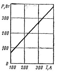
Rice. 3. Dependence of the power supplied by the CT on the primary current
In fig. 4 shows the dependencies showing which loads correspond to one or another class of VT accuracy.
However, VTs can operate with greater loads than given, but in this case the load must be limited so that the fault of the VT does not lead to incorrect operation of the relay protection and automation. Typically, VTs feeding only relay protection and automatic circuits operate in accuracy class 3.
Various semiconductor rectifiers and special power supplies are used as sources of rectified direct current. Direct current sources can be divided into three main groups:
-
battery charging and charging sources,
-
sources of operating current, supply circuits for control and signaling,
-
sources intended to power the electromagnets for switching on oil switches.
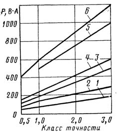
Rice. 4. Dependence of the TN accuracy class on the load: 1-NOM-6, 2-NOM-10, NTMI-6-66, NTMK-b-48, 3-NTMI-10-66,. NTMK-10, 4-NOM-35-66, 5-NKF-330, NKF-400, NKF-500, 6-NKF-110-57, NKF-220-55, NKF-110-48
Precharged capacitors should also be classified as current sources because they are charged through rectifiers fed from AC sources.
Rectifiers are used to charge and recharge batteries: VAZP, RTAB-4, VAZ, VSS, VSA, VU, etc.
In fig. 5 transmission block diagram of the regulator RTAB-4 is used in Mosenergo substations and is a rectifier semiconductor charger whose output voltage is automatically kept constant according to the specified setting.
The device is designed to work together with rechargeable batteries in charging mode. The RTAB-4 regulator covers the DC load of the substation as well as the natural self-discharge while providing stabilization of the indicated voltages and currents.
It consists of two voltage regulators — primary and secondary, operating independently of each other and acting on the primary and secondary elements of the battery. Regulation of the output voltage in each of the regulators is carried out by its own control circuit (measuring block IB and control block CU) acting on the rectifier of the power circuit.
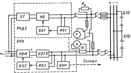
Rice. 5. Block diagram of the regulator RTAB -4: RNDE — voltage regulator of additional elements, ORN — main voltage regulator, DC — intermediate transformer, UV -controlled rectifier, BU1, BU2 — control blocks, IB1, IB2 — measuring units , UVM — Controlled Rectifier, BOTR — Regulatory Current Limiter, BKN — Voltage Control Unit, SEB — Main Battery Cells, BPA — Additional Battery Cells, Rd — Load Resistance of Additional Cells, W — Shunt
The voltage level in the DC buses is controlled by a special BKN unit that emits a signal when the voltage decreases or increases by 10% of the specified setting. The main regulator is equipped with a BOTR output current limiter for overload protection in the event of DC circuit failure and low battery operation.
The RTAB-4 regulator operates with natural air cooling at -5– + 30 ° C, the supply voltage is three-phase alternating current 220 or 380 V, the nominal rectified voltage at the output of the regulator is 220 V, the nominal output current is -50 A, the range of output current limit setting 40-80 A, control accuracy ± 2%.
The voltage regulator for additional elements is produced in two versions: for 20-40 and 40-80 V. Its maximum output current in normal mode is 1-3 A. The resistance Rd is used as a ballast load to discharge additional elements to avoid sulfation .
The operating circuits are powered by current blocks (BPT) and voltage blocks (BPN).
Blocks BPT (Fig. 6) consist of an intermediate saturated transformer PNT, a rectifier B, as well as auxiliary elements: a choke Dp and a capacitor C included in the output voltage stabilization circuit.
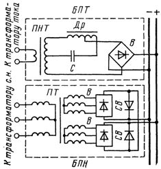
Rice. 6. Schematic diagram of power supplies BPT-1002 and BPN-1002
BPN units consist of intermediate transformer PT, rectifier B, rectifier SV and some other elements.
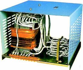
Rice. 7. Power supply unit BPN-1002
BPT units are supplied by TT and BPN by VT or transformers etc. BPT and BPN units or several BPT and BPN units usually operate on common rectified voltage buses. A characteristic difference between BPT and BPN units is that BPN units provide power to the operating circuits under normal operating conditions, when the substation is known to be energized, and BPT units — in short-circuit modes, when BPN units cannot provide power to the secondary devices due to the large voltage drop in the primary circuits.