Losses in AC wires
 When an alternating current flows through a conductor, an alternating magnetic flux is formed around and inside it, which induces e. d. s, which determines the inductive resistance of the wire.
If we divide the section of the current-carrying part into several elementary conductors, then those of them that are located in the center of the section and close to it will have the greatest inductive resistance, since they are covered by the entire magnetic flux - external and internal. Elementary conductors located on the surface are covered only by the external magnetic flux and therefore have the lowest inductive resistance.
Therefore, the elemental inductive resistance of the conductors increases from the surface towards the center of the conductor.
Due to the action of alternating magnetic flux, surface effect or skin effect, there is a displacement of flux and current from the axis of the conductor to its surface, in the outer elephant; the currents of the individual layers differ in magnitude and phase.
At a distance Z0 from the surface, the amplitude of the electric and magnetic fields and the current density decrease by e = 2.718 times and reach 36% of their initial value at the surface. This distance is called the penetration depth of the current field and is equal to
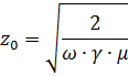
where ω is the angular frequency of the alternating current; γ — specific conductivity, 1 / ohm • cm, for copper γ = 57 • 104 1 / ohm • cm; µ = µ0 • µr µ0 = 4 • π • 10-9 gn / cm — magnetic constant; µr is the relative magnetic permeability, equal to 1 for copper and aluminum.
In practice, it is considered that the main part of the current passes into the surface layer of the conductor with a thickness equal to the penetration depth Z0, and the remaining part, internal, part of the cross section practically does not carry current and is not used for energy transfer .
In fig. 1 shows the current density distribution in a circular conductor at various ratios of conductor radius to penetration depth.
The field disappears completely at a distance from the surface equal to 4 — 6 Z0.
The following are the values of penetration depth Z0 in mm for some conductors at a frequency of 50 Hz:
Copper — 9.44, aluminum — 12.3, steel (µr = 200) — 1.8
The uneven distribution of the current along the cross-section of the conductor leads to a significant reduction in the cross-section of its actual current-carrying part and, therefore, to an increase in its active resistance.
As the active resistance of the conductor Ra increases, the heat losses in it I2Ra increase, and therefore, at the same value of the current, the losses in the conductor and the temperature of its heating with alternating current will always be greater than with direct current.
A measure of the surface effect is the surface effect coefficient kp, representing the ratio of the active resistance of the conductor Ra to its ohmic resistance R0 (at direct current).
The active resistance of the conductor is

The surface effect phenomenon is stronger the larger the cross section of the wire and its magnetic permeability and higher alternating current frequency.
In massive non-magnetic conductors, even at supply frequency, the surface effect is very pronounced. For example, the resistance of a 24 cm diameter round copper wire at 50 Hz alternating current is about 8 times higher than its resistance at direct current.
The skin effect coefficient will be the smaller, the greater the ohmic resistance of the conductor; for example, kn for copper wires will be greater than for aluminum of the same diameter (section), because the resistance of aluminum is 70% higher than copper. Since the resistance of the conductor increases with heating, the penetration depth will increase with increasing temperature and kn will decrease.
In wires made of magnetic materials (steel, cast iron, etc.), despite their high resistance, the surface effect manifests itself with extreme strength due to their high magnetic permeability.
The coefficient of surface effect for such wires, even with small cross-sections, is 8-9. Moreover, its value depends on the value of the current flowing. The nature of the resistance change corresponds to the magnetic permeability curve.
A similar phenomenon of current redistribution along the cross-section occurs due to the proximity effect, which is caused by the strong magnetic field of adjacent wires. The influence of the proximity effect can be taken into account using the proximity coefficient kb, both phenomena — the coefficient of additional losses:

For high-voltage installations with a sufficiently large distance between the phases, the coefficient of additional losses is mainly determined by the surface effect, since in this case the proximity effect is very weak. Therefore, in the following we consider the influence of only the surface effect on current-carrying conductors.
Rice. 1 shows that for large cross-sections only tubular or hollow conductors should be used, since in a solid conductor its middle part is not fully used for electrical purposes.
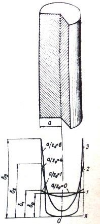
Rice. 1. Distribution of the current density in a round conductor at different ratios α / Z0
These conclusions are used in the design of current-carrying parts of high-voltage switches, disconnectors, in the design of busbars and busbars of high-voltage switchgear.
Determination of the active resistance Ra is one of the important problems related to the practical calculation of current-carrying parts and busbars with different profiles.
The active resistance of the conductor is determined empirically based on the measured total power losses in it, as a ratio of the total losses to the square of the current:

It is difficult to analytically determine the active resistance of a conductor, therefore, for practical calculations, calculated curves, constructed analytically and verified experimentally, are used.Typically, they allow you to find the skin effect factor as a function of some design parameter calculated from the conductor characteristics.
In fig. 2 shows curves for determining the surface effect of non-magnetic conductors. The surface effect coefficient from these curves is defined as kn = f (k1), a function of the calculated parameter k1, which is
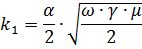
where α is the radius of the wire, see
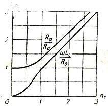
Rice. 2. Active and inductive resistance of the conductor at alternating current
At an industrial frequency of 50 Hz, it is possible to ignore the surface effect for copper conductors d <22 mm and for aluminum conductors d <30 mm, since for them kp <1.04
Loss of electrical energy can be carried out in non-current-carrying parts falling into an external alternating magnetic field.
Usually, in electrical machines, apparatus and switchgear, AC conductors must be located in close proximity to certain parts of the structure made of magnetic materials (steel, cast iron, etc.). Such parts include metal flanges of electrical equipment and supporting structures of busbars, distribution devices, reinforcement of reinforced concrete parts located near the buses, and others.
Under the influence of an alternating magnetic flux, a number of flowing currents arise in those parts that do not carry current eddy currents and their magnetization reversal occurs. Thus, energy losses occur in the surrounding steel structures from eddy currents and from hysteresiscompletely converted to heat.
The alternating magnetic flux in magnetic materials penetrates to a small depth Z0, measured, as is known, by a few millimeters.In this regard, eddy losses will also be concentrated in the thin outer layer Z0. Hysteresis losses will also occur in the same layer.
These and other losses can be accounted for separately or together using various, mostly semi-empirical formulas.