Overvoltage in electrical networks
 Overvoltage is a voltage that exceeds the amplitude of the highest operating voltage (Unom) on the insulation of the elements of the electrical network. Depending on the place of application, phase, inter-phase, internal windings and inter-contact overvoltage are distinguished. The latter occur when voltage is applied between open contacts of the same phases of switching devices (switches, disconnectors).
The following overvoltage characteristics are distinguished:
-
maximum value Umax or multiplicity k = umax / unom;
-
Duration of exposure;
-
curved shape;
-
The width of the range of network elements.
These characteristics are subject to statistical dispersion because they depend on many factors.
When studying the feasibility of surge protection measures and the choice of insulation, it is necessary to take into account the statistical characteristics of damage (mathematical expectation and deviation) due to downtime and emergency repairs of power system equipment, as well as due to equipment failure, rejection of the product and disruption of the technological process among electricity consumers.
The main types of overvoltage in high-voltage networks are shown in Figure 1.
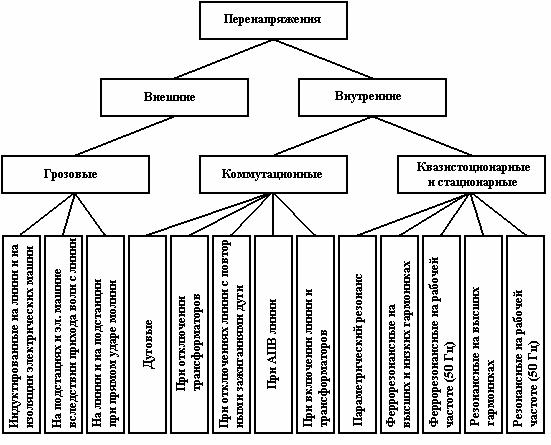
Rice. 1. The main types of overvoltage in high-voltage networks
Internal overvoltage caused by fluctuations in the electromagnetic energy stored in the elements of the electrical circuit or supplied to it by generators. Depending on the conditions of occurrence and the possible duration of exposure to insulation, stationary, quasi-stationary and switching overvoltages are distinguished.
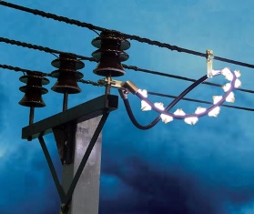
Switching overvoltages — occur during sudden changes in circuit or network parameters (planned and emergency switching of lines, transformers, etc.), as well as as a result of earth faults and between phases. When the elements of the electrical network (line conductors or windings of transformers and reactors) are switched on or off (interruption of the transmission of energy), oscillatory transients occur, which can lead to significant overvoltages. When corona occurs, the losses have a dampening effect on the first peaks of these overvoltages.
Interruption of capacitive currents of electrical circuits can be accompanied by repeated arcing in the circuit breaker and repeated transients and overvoltages and tripping of small inductive currents at idle speed of the transformers — forced interruption of the arc in the circuit breaker and oscillatory transition of the energy of the magnetic transformer field in the electric field energy of its parallel powers. With arcing earth faults in a network with an isolated neutral multiple arc strikes and the occurrence of corresponding arc surges are also observed.
The main reason for the occurrence of quasi-stationary overvoltages is the capacitive effect caused, for example, by a single-ended transmission line fed by generators.
Asymmetric line modes occurring, for example, when one phase is shorted to ground, a wire break, one or two phases of the circuit breaker, can cause the fundamental frequency voltage to increase further or cause overvoltages at some higher harmonics — multiple of the frequency of the EMF … generator.
Any element of the system with non-linear characteristics, for example a transformer with a saturated magnetic core, can also be a source of higher or lower harmonics and corresponding ferroresonant overvoltages. If there is a source of mechanical energy that periodically changes the circuit parameter (generator inductance) in time with the natural frequency of the electrical circuit, parametric resonance can occur.
In some cases, it is also necessary to take into account the possibility of internal overvoltages occurring with increased multiplicity when several commutations or other unfavorable factors are imposed.
To limit switching overvoltages in networks 330-750 kV, where the cost of insulation turns out to be particularly significant, powerful valve restrictors or reactors. In networks with lower voltage classes, arresters are not used to limit internal overvoltages, and the characteristics of lightning arresters are chosen so that they do not trip under internal overvoltages.
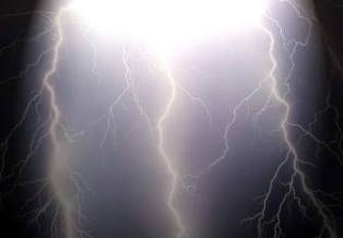
Lightning surges refer to external surges and occur when exposed to external emfs. The largest lightning surges occur when a direct lightning strike occurs on the line and substation. Due to electromagnetic induction, a nearby lightning strike creates an induced surge, which usually results in a further increase in insulation voltage. Reaching a substation or electrical machine, spreading from the point of defeat electromagnetic waves, can cause dangerous overvoltages on their insulation.
To ensure reliable operation of the network, it is necessary to implement its effective and economical lightning protection. Protection against direct lightning strikes is carried out with the help of a high vertical lightning rod and lightning protection cables above the conductors of overhead lines above 110 kV.
Protection against surges coming from the line is carried out by valve and pipe arresters of substations with improved lightning protection on approaches to substations on lines of all voltage classes.It is necessary to provide especially reliable lightning protection of rotating machines with the help of special arresters, capacitors, reactors, cable inserts and improved lightning protection for the overhead line approach.
The use of earthing of the neutral part of the network by means of an arc suppression coil, automatic reclosing and shortening of the lines, careful prevention of insulation, stops and earthing greatly increase the reliability of the lines.
It should be noted that the dielectric strength of the insulation decreases with increasing duration of exposure to voltage. In this regard, internal and external overvoltages of the same amplitude present a different danger to the insulation. Thus, the level of insulation cannot be characterized by a single withstand voltage value.
Selection of the required level of insulation, i.e. selection of test voltages, the so-called insulation coordination, is impossible without a thorough analysis of overvoltages occurring in the system.
The problem of insulation coordination is one of the main problems. This situation is due to the fact that the use of one or another nominal voltage is ultimately determined by the ratio between the cost of insulation and the cost of conductive elements in the system.
The isolation coordination problem includes as a basic task — setting the system isolation levels… The isolation coordination must be based on the specified amplitudes and waveforms of the applied overvoltages.
Currently, insulation coordination in the system up to 220 kV is done for atmospheric overvoltages, and above 220 kV coordination must be done taking into account internal overvoltages.
The essence of insulation coordination in atmospheric surges is the coordination (matching) of the impulse characteristics of the insulation with the characteristics of valves, as the main device for limiting atmospheric surges. According to the study, the standard wave of the test voltage is adopted.
When coordinating internal overvoltages, due to the greater variety of forms of development of internal overvoltages, it is impossible to focus on the use of a single protective device. The necessary brevity must be provided by the network scheme: shunt reactors, use of switches without re-ignition, use of special spark gaps.
For internal overvoltages, the normalization of insulation test waveforms has not yet been carried out until recently. A lot of material has already been accumulated and a corresponding normalization of the test waves is likely to be carried out in the near future.