Determination of active power in a three-phase network. Calculation example
 The active power in a three-phase network is determined by calculation as the sum of the powers of the phases P1, P2, P3 shown by individual wattmeters, i.e. P = P1 + P2 + P3, W
To measure power in a four-wire network, three-element wattmeters are often used, the scale of which is graduated in three-phase power values.
In three-wire three-phase current circuits, the active power is usually measured with two single-phase wattmeters or one three-phase two-element wattmeter, the scale of which is graduated in three-phase power values.
The active power P in a three-phase network, when measured by two single-phase wattmeters, is determined by calculation as the sum of the powers P'and P » measured by separate wattmeters, i.e. P = P '+ P' ', W .
It should be borne in mind that when measuring three-phase power with two wattmeters, their readings will be the same only when the phases are uniformly loaded and cosφ = 1. If cosφ = 0.5, then with uniform phase loading the readings of one wattmeter always will be zero.
With a uniform phase load and a cos value of φ less than 0.5, the needle of a wattmeter will deviate to the left of zero. Therefore, using a switch built into the device, you need to change the direction of the current in one of the coils of the wattmeter and read its readings with a minus sign.
In fig. 1 shows a diagram of the inclusion of three single-phase wattmeters with current transformers and additional resistances in a three-phase four-wire low-voltage network.
In this case, to determine the three-phase power, the power Px is first determined directly from the readings of the wattmeters, using the above formulas for determining the powers when the wattmeters are directly connected to the network according to the selected measurement scheme.
Then the obtained measurement result is multiplied by the transformation factor of the current transformer kt and the ratio of the nominal voltage U'nom of the parallel circuit, taking into account the external additional resistance to the nominal voltage Unominal parallel circuit without additional resistance.
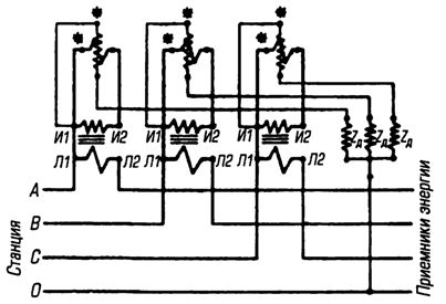
Rice. 1. Scheme for connecting three single-phase wattmeters with current transformers and additional resistances to a low-voltage three-phase current network
Example determination of active power in a three-phase network.
Determine the active power of the three-phase network 380/220 V according to the readings of three astatic wattmeters connected according to the scheme (Fig. 1) through current transformers with a nominal transformation ratio kt = 400/5. The voltage limit of the parallel circuit of wattmeters is extended from Unom = 150 V to U'nom = 400 V additional resistances. Wattmeter readings: P1 = 0.25 kW, P2 = 0.35 kW, P3 = 0.3 kW.
Answer.We determine the total power indicated by wattmeters: Px = P1 + P2 + P3 = 0.25 + 0.35 + 0.3 = 0.9 kW. The power of the three-phase network will be: P = Px x kt x (U'number /Unom) = 0.9 (400/5) (300/150) = 144 kW.
According to the diagram in fig. 1 also include separate circuits of two-element and three-element wattmeters.