RCD classification
 There are different types of residual current devices (RCDs) according to their design. Below is an approximate classification of RCDs.
1. Classification of RCDs by purpose:
-
RCDs without built-in overcurrent protection (differential current switches, see Fig. 1, a, b),
-
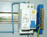
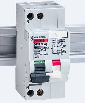
RCD with built-in protection against overcurrent (differential circuit breakers, fig. 2, a),
-
have thermal and electromagnetic releases and protect against overload and short circuit currents.
2. By the control method: RCD functionally independent of the voltage, RCD functionally dependent on the voltage (Fig. 2, b).
Residual current devices, functionally dependent on voltage, in turn, are subdivided into: devices that automatically open the power supply contacts in the event of a voltage interruption with or without a time delay. When the voltage is restored, some models of these devices automatically reclose the contacts of their main circuit, others remain in the disconnected state, to devices that do not open the power contacts when the voltage disappears.
There are also two versions of this group of devices.In one embodiment, when the voltage fails, the device does not open its contacts, but retains the ability to open the supply circuit when a differential current occurs. In the second variant, in the absence of voltage, the devices cannot stop when a differential current occurs.
RCDs functionally independent of the supply voltage (electromechanical). The source of energy required for operation — performing protective functions, including the trip operation, is the signal itself for the device — the differential current to which it responds, RCDs functionally dependent on the supply voltage (electronically). Their mechanism to perform the shutdown operation requires power obtained either from the monitored network or from an external source.
The reason for the smaller distribution of electronic RCDs is their inoperability when the neutral wire that supplies them is interrupted. In this case, the body of the electrical receiver, connected to the network through an RCD, which does not open its contacts when the voltage disappears, will be energized. In addition, despite their lower cost, their use is limited due to the lower reliability of electronic components.
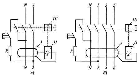
Rice. 1. Electrical diagrams of residual current devices: a — two-pole RCD, b — four-pole RCD, I — differential current transformer, II — comparison unit, III- disconnection unit, 1— 6 — phase conductors, N — neutral conductor, Azd> — designation of the block for comparing the differential current with the setting
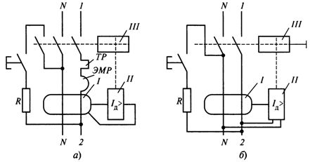
Rice. 2.RCD electrical circuits: a — with overcurrent protection (TP — thermal release, EMR — electromagnetic release), b — with an electronic comparison device (II) powered from the network, I — differential current transformer, II — comparison unit, III — shutdown block
3. By installation method:
-
RCDs used for stationary installation,
-
Portable RCD devices, including those connected by cable. This is, for example, a type A RCD plug plugged into a socket with a grounding contact, having a «Test» button with rated currents: working — 16 A, differential — 30 mA.
4. According to the number of poles and current paths, the most common:
-
two-pole RCDs with two protected poles,
-
four-pole RCD with four protected poles.
A number of manufacturers also produce three-pole RCDs with overcurrent protection.
5... According to the conditions of regulation of the tripping differential current:
-
An RCD with a single rated residual breaking current value,
-
RCD with several fixed values of tripping differential current.
6. According to the conditions of operation in the presence of a DC component:
-
AC type RCDs responding to sinusoidal alternating differential current, slowly rising or suddenly occurring,
-
Type A RCDs responding to both sinusoidal alternating differential current and pulsating direct current differential current, slowly rising or occurring during a spike,
-
U30 Type B responding to both sinusoidal AC differential current and pulsating DC differential current, slowly rising or spiking as well as DC responsive.
7. By having a time delay:
-
RCD without time delay — general use type,
-
Time-delayed RCD — Type S (optional).
In branched power supply systems, RCDs with different values of rated differential currents and tripping times are used. A selective RCD (type S) with a differential current of 300 or 500 mA is installed at the beginning of the network. Selective RCDs are also available for 1000 and 1500 mA currents.
To exclude false alarms with a short-term increase in leakage current, as well as to ensure earlier operation of the RCD at subsequent power levels, selective RCDs have a tripping time of 130 — 500 ms
Residual current devices with a residual current of 30 mA perform the function of protection against electric shock, and selective RCDs with a current of 300 mA provide fire protection.
In case of insulation failure and a differential current flow of 300 mA or more, the RCD of the lower protection level with a current of 30 mA will operate first. In this case, a selective RCD with a longer tripping time will not work and the power supply to the undamaged electrical consumers will remain.
8. By the method of protection against external influences:
-
RCDs with a protective design that do not require a protective casing for their operation,
-
RCDs with an unprotected design, for which a protective casing is required for operation.
9. By way of installation:
-
RCD for surface mounting,
-
Built-in RCD,
-
Panel-to-panel RCD installation.
10. According to the instantaneous tripping characteristic (for RCDs with built-in overcurrent protection):
-
RCD type B,
-
RCD type C,
-
RCD type D.