Overvoltage in the transformer windings
 The sizing and design selection of transformer insulation is impossible without determining the stresses acting on various sections of the transformer insulation during operation and testing designed to ensure reliable operation of the transformer.
In this case, the voltages acting on the transformer insulation when lightning surge waves strike its input are often decisive. These voltages, also called impulse voltages, in almost all cases determine the choice of longitudinal winding insulation and in many cases the main winding insulation, switching device insulation, etc.
The use of computer technologies in the determination of overvoltages allows to move from a qualitative consideration of impulse processes in windings to direct calculations of overvoltages and the introduction of their results into design practice.
To calculate the overvoltage, the windings of the transformer are represented by an equivalent circuit that reproduces inductive and capacitive connections between the elements of the winding (Figure 1).All equivalent circuits consider the capacitance between turns and between windings.
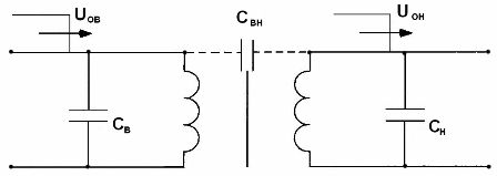
Figure 1. Equivalent circuit of the transformer: UOV — incident wave in the high voltage winding, UOH — incident wave in the low voltage winding, SV and CH — capacitances between the turns of the high and low voltage windings respectively, SVN — capacitance between windings with high and low voltage.
Wave processes in transformers
The transformer will be considered as an inductive element, taking into account the interturn capacitance, the capacitances between the screen and the inductance, and between the inductance and ground (Figure 2a).
The following formulas are used to calculate overvoltage:
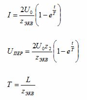
where: t is the time after the arrival of the wave to the transformer, T is the overvoltage time constant, ZEKV is the equivalent circuit resistance, Z2 is the line resistance, Uo is the overvoltage at the initial time
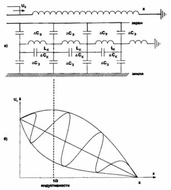
Figure 2. Propagation of a voltage wave along the winding of a transformer with a grounded neutral: a) schematic diagram, b) dependence of the voltage wave on the length of the winding for a single-phase transformer with a grounded terminal: Uo — drop voltage wave, ∆Ce — capacitance between the coil and the screen, ∆Ck — inherent capacitance between the turns, ∆С3 — capacitance between the coil and the ground, ∆Lк — inductance of the coil layers.
Since there is both inductance and capacitance in the equivalent circuit, an oscillating LC circuit occurs (the voltage fluctuations are shown in Figure 2b).
The amplitude of the oscillations is 1.3 — 1.4 of the amplitude of the incident wave, i.e.Uпep = (1.3-1.4) Uo, and the largest value of overvoltage will occur at the end of the first third of the winding, therefore, in the construction of the transformer, 1/3 of the winding has reinforced insulation compared to the rest .
To avoid overvoltage, the charging current of the capacitors with respect to ground must be compensated. For this purpose, an additional screen (shield) is installed in the circuit. When using the screen, the capacitances of the windings to the screen will be equal to the capacitance of the turns to earth, i.e. ∆CE = ∆C3.
Shielding is performed in transformers with voltage class UH = 110 kV and higher. The shield is usually installed near the transformer casing.
Single-phase transformers with isolated neutral
The presence of an isolated neutral means that there is a capacitance Co between the earth and the winding, ie the capacitance is added to the equivalent circuit of the earth terminal transformer, but the screen is removed (Figure 3a).
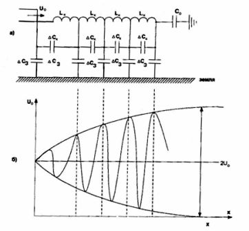
Figure 3. Propagation of a voltage wave along the winding of a transformer with an isolated neutral: a) schematic diagram of an equivalent transformer, b) the dependence of the incident wave voltage on the length of the winding.
An oscillating circuit is also formed with this equivalent circuit. However, due to the capacitance Co, there is an oscillating LC circuit with a series connection of inductance and capacitance. In this case, with a significant capacitance Co, the highest voltage will appear at the end of the winding (the overvoltage can reach values up to 2Uo). The nature of the voltage change across the coil is shown in Figure 3b.
To reduce the amplitude of overvoltage oscillations in the winding of a transformer with an isolated neutral, it is necessary to reduce the capacitance of the output C with respect to ground or to increase the self-capacitance of the coils. The latter method is usually used. In order to increase the self-capacitance ∆Ck between the coils of the high-voltage winding, special capacitor plates (rings) are included in the circuit.
Wave processes in three-phase transformers
In three-phase transformers, the nature of the incident wave propagation process along the winding and the magnitude of overvoltages are influenced by:
a) coil connection diagram,
b) the number of phases to which the surge wave arrives.
A three-phase transformer with a high-voltage winding, star connected with a solidly grounded neutral
Let the incident surge wave come into one phase of the transformer (Figure 4).
The processes of propagation of overvoltage waves along the windings in this case will be similar to the processes in a single-phase transformer with a grounded neutral (in each of the phases the highest voltage will be in 1/3 of the winding), while they do not depend on how much phases reaches the surge wave. These. the value of the overvoltage in this part of the coil is equal to Upep = (1.3-1.4) Uo
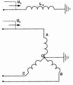
Figure 4. Equivalent circuit of a three-phase transformer with a high-voltage winding connected to a star with a neutral earthed network. The surge wave comes in one phase.
Three-phase star-connected high-voltage transformer with isolated neutral
Let the surge wave come in one phase.The equivalent circuit of the transformer, as well as the propagation of the incident wave in the transformer winding, is shown in Figure 5.
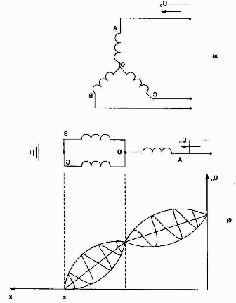
Figure 5. Equivalent circuit of a three-phase transformer with a star-connected high-voltage winding (a) and the dependence U = f (x) for the case when the wave comes in one phase (b).
In this case, two separate oscillation zones appear. In phase A there will be one oscillation range and the conditions under which they occur, and in phases B and C there will be another oscillation loop, the oscillation range will also be different in both cases. The largest overvoltage will be on the winding receiving the incident surge wave. At the zero point, overvoltages up to 2/3 Uo are possible (in normal mode at this moment U = 0, therefore, overvoltages with respect to the operating voltage Uoperation are the most dangerous for it, since U0 >> Uoperation).
Let the surge wave pass through two phases A and B. The equivalent circuit of the transformer as well as the incident wave propagation in the transformer winding is shown in figure 6.
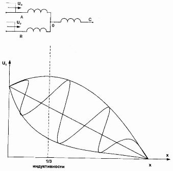
Figure 6. Equivalent circuit of a three-phase transformer with a star-connected high-voltage winding (a) and the dependence U = f (x) for the case when the wave comes in two phases.
In the windings of the phases to which the wave comes, the voltage will be (1.3 — 1.4) Uo. The neutral voltage is 4/3 Uo. To protect against overvoltage in this case, an arrester is connected to the neutral of the transformer.
Let the surge wave come in three phases. The equivalent circuit of the transformer as well as the propagation of the incident wave in the transformer winding is shown in Figure 7.
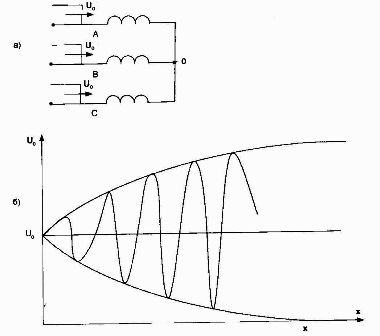
Figure 7.Equivalent circuit of a three-phase transformer with a star-connected high-voltage winding (a) and the dependence U = f (x) for the case when the wave comes in three phases.
The propagation processes of an overvoltage drop wave in each of the phases of a three-phase transformer will be similar to the processes in a single-phase transformer with an isolated output. The highest voltage in this mode will be in neutral and will be 2U0. This case of transformer overvoltage is the most severe.
Three-phase high-voltage delta-wound transformer
Let the surge wave pass through one phase A of a three-phase high-voltage transformer connected in a delta, the other two phases (B and C) are considered grounded (Figure 8).
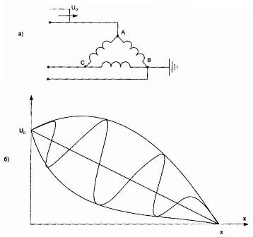
Figure 8. Equivalent circuit of a three-phase transformer with a high-voltage winding connected in delta (a) and the dependence U = f (x) for the case when the wave comes in one phase.
Windings AC and BC will be exposed to an overvoltage (1.3 — 1.4) Uo. These overvoltages are not dangerous for the operation of the transformer.
Let the overvoltage wave come in two phases (A and B), the explanatory graphs are shown in Figure 9. In this mode, the propagation of overvoltage waves in the windings AB and BC will be similar to the processes in the corresponding windings of a three-phase grounded transformer terminal. These. in these windings the overvoltage value will be (1.3 — 1.4) Uo and in the AC winding it will reach the value (1.8 — 1.9) Uo.

Figure 9. Dependence U = f (x) for the case when the overvoltage wave passes through two phases of a three-phase transformer with a high-voltage winding connected in delta.
Let surge waves pass through all three phases of a three-phase transformer with a high-voltage delta-connected winding.
The windings of all phases in this mode will be exposed to an overvoltage (1.8 — 1.9) Uo. If a surge wave comes simultaneously through two or three wires, then in the middle of the winding, to which the waves come from both sides, voltage fluctuations with an amplitude that are dangerous for the operation of the transformer may occur.
Transformer surge protection
The most dangerous overvoltages of the main insulation of the windings can occur in the case of simultaneous arrival of waves through three wires to the transformer with a delta connection (in the middle of the winding) or a star with an isolated neutral (almost neutral). In this case, the amplitudes of the resulting overvoltages approach twice the voltage of the output or four times the amplitude of the input wave. Dangerous turn-to-turn insulation overvoltages can occur in all cases when a wave with a steep front arrives at the transformer, regardless of the connection scheme of the transformer windings.
Thus, for all transformers in the event of overvoltages and their distribution along the windings, in order to estimate their magnitude, it is necessary to take into account the capacitances in the equivalent circuits of the transformers (and not only the inductance). The accuracy of the overvoltage values obtained depends largely on the accuracy of the capacitance measurement.
In order to avoid overvoltages in the design of transformers, it is provided:
-
an additional screen that distributes the charging current, therefore, overvoltages are reduced.Also, the screen reduces the field strength at certain points on the transformer winding,
-
strengthening the insulation of the windings in certain parts of it (constructive replacement of the windings of the transformer),
-
installation of arresters in front of the transformer and after it — against external and internal overvoltages, as well as an arrester in the neutral of the transformer.