Three-phase EMF system
Three-phase electrical circuits are a special case of polyphase circuits. A polyphase system of electric circuits is a combination of several single-phase electric circuits, each of which has sinusoidal EMFs of the same frequency, created by a common energy source and shifted relative to each other in phase at the same angle. The term «phase» is used to denote an angle characterizing the stage of a periodic process, as well as to name a single-phase circuit included in a multi-phase circuit.
Usually, symmetrical polyphase systems are used, where the values of the EMF amplitudes are the same, and the phases are shifted relative to each other at the same angle 2π / m, where m is the number of phases. Two-phase, three-phase, six-phase circuits are most often used in electrical engineering. In the power industry, three-phase systems are of the greatest practical importance.
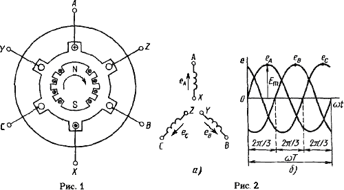
Three-phase circuits are a combination of three single-phase circuits in which sinusoidal EMFs of the same frequency act phase-shifted relative to each other by an angle of 2π/3.The source of electrical energy in a three-phase circuit is a synchronous generator, in three windings of which, structurally displaced relative to each other by an angle of 2π/3 and called phases, three EMFs are induced, in turn, also displaced relative to each other by an angle of 2π/ 3. The device of a three-phase synchronous generator is schematically shown in fig. 1.

Three identical windings are located in the channels of the stator core. At the front end of the stator, the turns of the windings terminate at terminals A, B, C (the beginning of the windings) and respectively at terminals X, Y, Z (the ends of the windings). The beginnings of the windings are displaced relative to each other by an angle of 2π/3, and accordingly their ends are also displaced relative to each other by an angle of 2π / 3 EMF in the stator windings is induced as a result of the crossing of their turns by a magnetic field that is excited from a direct current passing through the winding of the rotating rotor, which is called the field winding. At the same rotor speed, sinusoidal EMFs of the same frequency are induced in the stator windings, out of phase relative to each other by an angle of 2π/3.
A three-phase system of EMF induced in the stator of a synchronous generator is usually a symmetrical system.
On electrical circuits, the stator windings of a three-phase generator are conventionally depicted as shown in fig. 2 (a). For the conditional positive direction of the emf in each phase of the generator, the direction from the end to the beginning of the winding is taken.

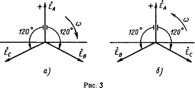
In fig. 2 (b) shows the change in instantaneous EMF values of a three-phase generator, and in fig. 3 (a, b) shows their vector diagrams for the forward and reverse phase sequence.The sequence in which the EMF in the phase windings of the generator assumes the same values is called phase sequence or phase sequence. If the rotor of the generator is rotated in the direction shown in fig. 1, then the phasing sequence ABC is obtained, i.e. The EMF of phase B lags the EMF of phase A and the EMF of phase C lags the EMF of phase B.
This EMF system is called a direct sequence system… If you reverse the direction of rotation of the generator rotor, then the phase sequence will be reversed. In generators, the rotors always rotate in the same direction, so the phase sequence never changes.
In practice, generators usually use direct phase sequence. The direction of rotation of three-phase synchronous and asynchronous motors depends on the phase sequence. It is sufficient to switch any two phases of the motor, since there is a reverse phase sequence and therefore the opposite direction of rotation of the motor.
Phase sequence must also be considered when connecting three-phase generators in parallel.
