Electrical equipment of elevators
 An elevator is a cyclic lifting machine designed for vertical lifting of people and goods. By appointment, the elevators are divided into passenger, cargo-passenger, hospital, cargo.
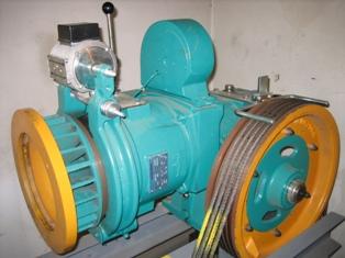
Depending on the speed of the car, elevators are divided into low-speed (up to 0.71 m / sec), high-speed (from 1 to 1.6 m / sec), high-speed (from 2 to 4 m / sec) and high-speed (4 — 10 m / s) ... The load capacity of passenger elevators is from 320 to 1600 kg, freight elevators - from 160-5000 kg. At a speed of up to 1.6 m / sec, the electric motor is connected to the traction beam through a gearbox, if the speed is higher, then gearless electric drives are used.
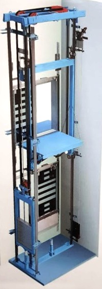
With a wide variety of design options for passenger and freight elevators, the main devices for them are hoist, ropes, car, counterweight, mechanical brake and control equipment. Modern elevators have a counterweight suspension system and a counterweight rope.
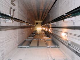
The cabin moves along vertical rails.The cabin is suspended from the ropes that surround the towing wire and guide the pulleys of the electric winch drive. At the ends of the rope there is a counterweight that moves along the guides. The counterweight mass is equal to the sum of the cabin mass and (0.42 — 0.5) the load mass (or half of the most likely cabin load).
Elevator drives
In elevators and freight elevators, the types of electric drives are selected depending on the speed of movement, the number of floors of the building and the required braking accuracy. The following electric drives are currently in use:
a) for buildings up to 17 floors, low-speed and high-speed elevators with a speed of 0.7 to 1.4 m / s with a load capacity of 320, 400 kg are used. These elevators use an electric drive with an asynchronous two-speed electric motor with a rotor in a squirrel cage,
b) for high-speed passenger elevators with a speed of 1.6 m / s, intended for buildings up to 25 floors, an electric drive according to the thyristor voltage regulator system (TRN) with a two-speed asynchronous motor (TRN-ADD ) is used.
The presence of an adjustable electric drive ensures high smoothness of acceleration and deceleration processes, high accuracy of stopping on the floor (up to 20 mm) and the absence of a section with reduced speed before stopping. The second winding of the motor is used to achieve low speed during overhaul,
c) for high-speed and high-speed elevators, constant electric drives according to the motor system of thyristor converter-TP-D and alternating current according to the system of frequency converter-short-circuit asynchronous electric motor GGCH-AD are used.
Thyristor electric drive from elevator type ULMP-25-16
The power supply of the electric drive (Fig. 1) is carried out by a reversible thyristor voltage regulator UZ (TRN) at start-up and uniform movement and by a separate rectifier assembled according to a single-phase bridge circuit UZ1 for powering the stator winding during dynamic braking.
The system provides parametric phase control of the rotational speed of a squirrel-cage induction motor. The automatic control system is made on a single-chip microcomputer of the KR1816VB031 type, which performs direct digital control of the rotation speed of a two-speed asynchronous electric motor.
The automatic control system ensures high accuracy of maintaining the set speed and stopping at the level of the required floor directly to the set point without a section with reduced speed. The second winding of the motor is turned on only during overhaul.
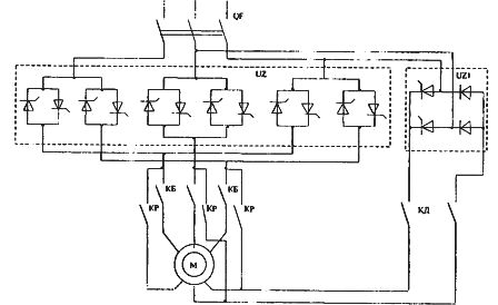
Rice. 1. Scheme of the thyristor electric drive of the elevator
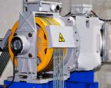
Brake solenoids
Lifting mechanisms of elevators are equipped with special braking devices with short-stroke and short-stroke direct current electromagnets, which are connected to a 220 or 380 V network through a rectifier.
Elevator control devices
Floor switches designed for switching motion control circuits. They register the position of the car, automatically select the direction of movement («up» or «down») and give a command to turn off the electric drive when braking.Structurally, these are three-position (1-0-2) three-point lever switches (motion control devices) having movable (on the lever) to fixed (on-body) contacts.
The floor switches are mounted in the shaft at floor level and there is a molded branch in the cab that acts on the floor switch lever.
When the cabin moves "up" by turning the lever, one group of fixed contacts closes, and "down" - another. When the car is at floor level, the floor switch is in the neutral position «O» and the fixed contacts are open.
Speed switches are designed to give an impulse to reduce speed before stopping the vehicle. They are used in high-speed elevators with electric drive with two speed execution. They are built on the principle of floor switches, but have a different design. The speed switches are installed in the mine shaft as a complete set above and below the floor at a distance of 0.5 to 0.6 m.
Lever switches are designed to operate controlled freight elevators. Structurally, these are three-position lever switches with self-return of the handle to the neutral position ("top" -0- "bottom"), mounted in the cabin. By turning the handle, the direction of movement is selected, which is achieved by closing a pair of fixed contacts. When the handle is released, the contacts open and the motor stops (turns off). The switches are used simultaneously as a limit switch in the end positions of the cab. This is achieved by the action of the lever on the roller of special guides in the shaft of the mine.
Inductive sensors designed for use in high-speed elevators. The diagram of such sensors for alternating and rectified current is shown in Fig. 2.
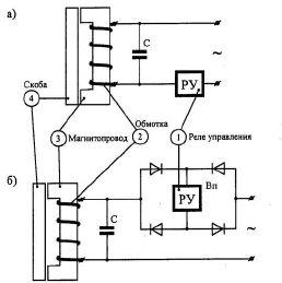
Rice. 2. Schematic diagram of alternating (a) and rectified (b) current inductive sensors
A U-shaped laminated magnetic circuit made of steel 3 is installed in the mine shaft, and there is a steel bracket 4 on the cabin, which is a magnetic shunt. On the magnetic circuit there is a coil with winding 2, to which the control relay 1 is connected directly or through a Vp rectifier. When the clamp leaves (the magnetic circuit opens), the inductive resistance of the coil is small, which will ensure the operation of the control relay. If the steel bracket overlaps the magnetic circuit, the inductive resistance of the coil rises sharply and the relay is released.
The reliability and clarity of operation of the control relay is ensured by the inclusion of capacitance C in parallel with the coil, which is selected from the condition of obtaining a mode close to the resonance of currents. The use of a rectifier to power the control relay increases the reliability of the operation of the magnetic system of the relay.
In addition, hermetic contact devices (reed switches) are widely used in travel sensors. The use of inductive sensors eliminates such disadvantages of floor switches and speed switches as noise and radio interference arising from the operation of contact devices.
Magnetic layering is an electromagnetic device installed in the cabin and controlling the operation of the mine door locks. The magnetic branch limiter is connected to the armature of the branch electromagnet.When the cab is on the floor, the branch electromagnet is de-aerated, the spring-loaded detent disengages the mine door lock latch, allowing it to open.
When moving, the electromagnet of the branch is energized — the latch is introduced, which prohibits opening the door. Such locks are used in elevators of old design (or modernized) with manual shaft door operation.
Automation of elevators
The main difference between the operation of elevators and hoists is their multi-position position, which is expressed in the fact that the mechanisms can occupy a large number of fixed positions. Therefore, after each stop it is necessary to solve the logical problem of choosing the next move. The solution to this problem is currently implemented using logic chips and microprocessors. The following tasks are set for the elevator control scheme: control of the position of the car in the shaft, automatic selection of the direction of movement, determination of the starting time of the stop, accurate stopping of the car on the floor, automatic opening and closing of doors and protection of electric drives and elevator.
The command signals that set the car's motion program are divided into two types: "orders" coming from the car and "calls" coming from the landing pad. Commands are given via buttons located in the cockpit and floor areas respectively. Depending on the response to commands and the methods of their processing, separate and collective control schemes differ.With a separate control principle, the circuit perceives and executes only one command and during its execution does not respond to other orders and calls.
This scheme is the simplest to implement, but limits the possible characteristics of the elevator and is therefore only used for elevators in residential buildings up to nine floors high with a relatively small flow of passengers. With the principle of collective control, the circuit receives several commands simultaneously and executes them in a certain sequence, usually in the order of the floors.
The basis of the elevator control system is the floor clock measurement. The study of the clock can be a pendulum, when the fixing is carried out in two directions, from the bottom up and from the top down, and in one direction, for example, only from the top down. The pendulum swing is used more often.