Switching circuit of a wattmeter
 A wattmeter is used to directly measure the power of a DC circuit. The fixed series coil or current coil of the wattmeter is connected in series with the receivers of electrical energy. A movable parallel coil or voltage coil connected in series with an additional resistance forms the parallel circuit of the wattmeter, which is connected in parallel with the energy receivers.
Angle of rotation of the movable part of the wattmeter:
α = k2IIu = k2U / Ru
where I — series coil current; Azi — the current of the parallel coil of the wattmeter.
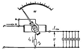
Rice. 1. Schematic of the device and connections of the wattmeter
Since, as a result of the use of additional resistance, the parallel circuit of the wattmeter has an almost constant resistance rth, then α = (k2 / Ru) IU = k2IU = k3P
Thus, by the angle of rotation of the movable part of the wattmeter, the power of the circuit can be estimated.
Wattmeter uniform scale.When working with a wattmeter, it should be borne in mind that a change in the direction of the current in one of the coils causes a change in the direction of the torque and the direction of rotation of the moving coil, and since the scale of the wattmeter is usually made one-sided, that is, the divisions of scale are located from zero to the right, then with the wrong direction of current in one of the coils, it will be impossible to determine the measured value from the wattmeter.
For these reasons, you should always distinguish between the wattmeter clamps. The terminal of the series coil connected to the power source is called the generator and is marked on the devices and diagrams with an asterisk. A parallel circuit clamp connected to a wire connected to a series coil is also called a generator clamp and is marked with an asterisk.
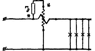
Thus, with the correct wattmeter switching circuit, the currents in the wattmeter windings are directed from the generator terminals to the non-generator terminals. There may be two wattmeter switching circuits (see Fig. 2 and Fig. 3).
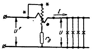
Rice. 2. Correct wattmeter wiring diagram
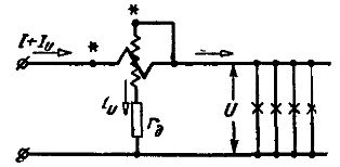
Rice. 3. Correct wattmeter wiring diagram
In the scheme shown in fig. 2, the current of the series winding of the wattmeter is equal to the current of the energy receivers whose power is measured, and the parallel circuit of the wattmeter is under a voltage U' greater than the voltage of the receivers by the amount of the voltage drop in the series coil. Therefore, PB = IU '= I (U + U1) = IU = IU1 the power measured by the wattmeter is equal to the power of the energy receivers to be measured and the power of the series winding of the wattmeter.
In the scheme shown in fig.3, the voltage in the parallel circuit of the wattmeter is equal to the voltage of the receivers, and the current in the series coil is greater than the current consumed by the receiver by the value of the current in the parallel circuit of the wattmeter. Therefore, Pc = U (I + Iu) = UI + UIu, the power measured by the wattmeter is equal to the power of the receivers of the measured energy and the power of the parallel circuit of the wattmeter.
When making measurements where the power of the wattmeter coils can be neglected, it is preferable to use the circuit shown in Fig. 2, because usually the power of the series coil is less than the parallel coil and therefore the wattmeter reading will be more accurate.
For accurate measurements, it is necessary to make corrections to the readings of the wattmeter, due to the strength of its winding, and in such cases the circuit of Fig. 3, since the correction is easily calculated by the formula U2/ Ru, where Ru is usually known and the correction remains unchanged at different current values if U is constant.
When you turn on the wattmeter according to the diagram in fig. 2, the potentials at the ends of the coils differ only by the amount of voltage drop across the moving coil, as the generator terminals of the coils are connected together. The voltage drop across the moving coil is negligible compared to the voltage in the parallel circuit because the resistance of this coil is negligible compared to the resistance of the parallel circuit.
Rice. 4. Wrong wattmeter connection circuit
In fig. 4 an incorrect parallel circuit of a wattmeter is given.Here, the generator terminals of the windings are connected by additional resistance, as a result of which the potential difference between the ends of the coils is equal to the circuit voltage (sometimes very significant 240 — 600 V), and since the stationary and moving windings are in close proximity next to each other, conditions are created favorable for the destruction of the insulation of the coils. In addition, electrostatic interaction will be observed between coils of very different potentials, which can cause additional error in the power measurement in the circuit.