Phase meters and synchroscopes
 Phase meters are used to determine the phase angle, for example, of an alternating current with respect to the voltage causing it.
The stationary part of the measuring mechanism of the phase meter includes three coils, two of which 1 and 2 have the shape of frames. They are shifted relative to each other at an angle of 120 ° (Fig. 1, a). The cylindrical coil 3 is located inside the coils 1 and 2 coaxially with the movable part.
The movable part is formed by an axis 4, to the ends of which are attached cores 5 in the form of thin plates, offset from each other by 180 ° and called petals. The axis and petals are made of soft magnetic material and form a Z-shaped structure (Fig. 1, b). The measuring mechanism does not have an opposite moment created by the spring, therefore the device in question can be attributed to ratios.
In fig. 2 shows the scheme for switching on the phase meter. Windings 1 and 2 are included in the cut of two wires of a three-phase line, and winding 3 is in series with a resistor Rd, which has a significant active resistance, is connected to the mains voltage.The linear currents flowing through these windings are shifted relative to each other in phase by 120 °, in connection with which windings 1 and 2 create a rotating magnetic flux Ф12, as if they represented a load current vector. The frequency of its rotation depends on the frequency of the currents I1 and I2... In one period, the flow F12 makes one complete revolution.
Since the resistance of the resistor Rq is large compared to the reactance of the coil 3, the current Az3 is in phase with the line voltage. Coil 3, as a result of a sinusoidal change in current, creates a pulsating magnetic flux F3, which is close to sinusoidal. The axis of symmetry of this flow is stationary in space and always coincides with the axis of the moving part of the mechanism. The flux F3 is closed along the axis 4 of the movable part, the petals and the fixed external cylindrical magnetic circuit.
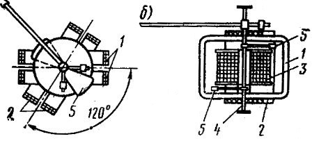
Rice. 1. Z-shaped core electromagnetic system ratio measuring mechanism
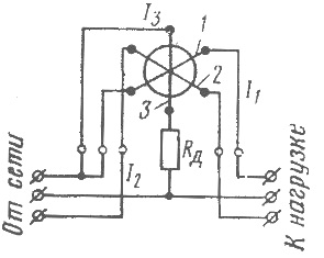
Rice. 2. Circuit diagram of the phase meter of the electromagnetic system
The fluxes F12 and F3, closed in different planes, magnetize the moving part of the measuring mechanism. Since the value of the flux Ф12 is constant, the magnetization of the axis and petals reaches the highest value at the moment when the flux Ф3 passes through the largest value. Due to the action of inertial forces, the movable part is fixed motionless in a position corresponding to its greatest magnetization, i.e. the position of the rotating flux Ф12 at the moment when the flux Ф3 reaches its maximum value.
It should be borne in mind that the position of the rotating flux relative to the stationary part of the device at the moment of passage of the flux Ф3 and the current Аз3 through the value of the amplitude depends on the angle φ change between the load current and the voltage. Given this, the position occupied by the moving part (and, accordingly, the pointer of the device) with respect to the scale, i.e. the angle α characterizes the phase shift between the load current and voltage.
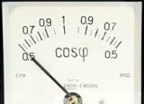
A phasometer working on this principle measures phase shifts with capacitive and inductive loads. The scale of the device can be graduated in angular values φ or cosφ... In the first case it is uniform, in the second it is uneven.
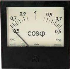
Phasometer Ts302
Synchronoscopes
The measuring mechanism under consideration is also used in the synchroscope, a device used when connecting synchronous generators for parallel operation.
The diagram for switching on the synchroscope is shown in fig. 3.
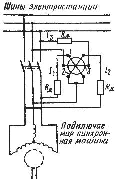
Rice. 3. Circuit diagram of the synchronoscope of the electromagnetic system
The construction of the coils 1, 2 and 3 of the measuring mechanism is similar to the construction of the corresponding coils of the phase meter, but they are made of thin copper wire with a large number of turns, as a result of which the coils have a significant resistance. Coil 3 is connected to the line voltage of the network, coils 1 and 2 — to the line voltages of the connected synchronous machine. The resistors are connected in series with the coils R and so on.
As mentioned, the moving part of the measuring mechanism is mounted in the resulting magnetic field of the three coils so that the axis of the lobes of the moving part coincides with the direction of the rotating field Ф12, in which it will be captured by the amplitude value of the pulsating field F3.
This position of the lobes of the moving part at the same frequency of the current in the windings of the coils depends on the phase shift between the currents I1 and Az2 in the windings of the coils 1, 2 and the current Az3 in the winding of the coil 3. Currents I1 and Az2 practically coincide in phase with the line voltage of the synchronous generator and the current Az3 — with the mains voltage (from the resistance of the resistor Rq is great).
As a consequence ° С Thus, the indicating device of the synchroscope, when the frequencies of the mains current and the connected generator are equal, will directly indicate the phase shift between the line voltages of these three-phase systems.
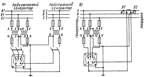
Rice. 4. Connection diagrams: a — synchroscope, b — phasometer of the electromagnetic system
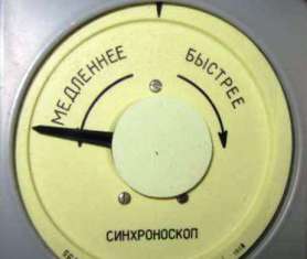
Rice. 5. Synchronoscope type E1605
When synchronizing, the frequency of the mains current and the current of the connected generator are not the same. This results in a continuous change in the phase angle between the line voltage and e. etc. v. generator and therefore to a change in the position of the petals relative to the stationary coils. Since the movable part of the synchroscope can be rotated to any angle, the pointer rotates.
The direction of rotation depends on the sign of the frequency difference between the mains and the connected generator. The smaller this difference, the slower the rotation of the synchroscope pointer.
The scale of the device has a sign corresponding to the antiphase position of the voltage vectors and e. etc.v. synchronized objects. The synchronous machine must be connected to the station buses during the gas mask position of the vectors of e. etc. pp. and bus voltages.
In fig. 4 shows a wiring diagram of an electromagnetic phase meter and a wiring diagram of an electromagnetic synchroscope.