Bridge measurements
 Bridge circuit — a scheme for connecting the elements of an electrical circuit (resistances, rectifier diodes, etc.), characterized by the presence of a bridge branch between two points of the circuit that are not directly connected to the source of electrical energy. The bridge circuit is based on the Wheatstone Bridge circuit (Fig. 1).
The principle of operation of the bridge circuit is based on the fact that when the ratio of impedances in the arms of the bridge is equal to За / Зб = ЗНС/Зд there is no current in the diagonal of the bridge (in the indicator device). By increasing the sensitivity of the zero indicator, it is possible to achieve very accurate equality of impedance ratios in the bridge circuit. Bridge measurements are based on this principle.
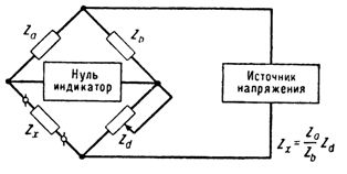
Rice. 1. Bridge Diagram (Wheatstone Bridge Diagram)
Power supplies for bridge circuits can be either DC or AC sources. Bridge balancing is completely independent of supply voltage fluctuations.
Bridge measurements — Methods for measuring the parameters of electric circuits of direct current (DC resistance, current) and of alternating current (active resistance, capacitance, inductance, mutual inductance, frequency, angle of loss, quality factor, etc.) by means of bridge chains. Bridge measurements are also widely used for electrical measurements of non-electric quantities using sensors — intermediate converters of the measured quantity into a functionally related parameter of the electrical circuit.
Bridge measurements are carried out using measuring bridges (bridge installations) belonging to the category of comparison devices. In general, they are based on the use of a certain electrical circuit consisting of several known and one unknown (measured) resistance, powered by a single source and equipped with an indicator device.
By changing the known resistances, this circuit is adjusted until a certain, indicated by the pointer, distribution of voltages in individual sections of the circuit is reached. It is obvious that a given ratio of voltages also corresponds to a definite ratio of circuit resistances, by which it is possible to calculate the unknown resistance if the other resistances are known.
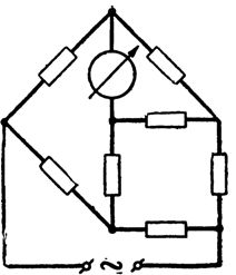
Historically, the first, simplest and most common version of bridge measurements was realized by means of a balanced bridge with four arms, which is a ring circuit of 4 resistors ("arm" bridges), in which the power supply and the pointer are connected diagonally to opposite vertices, under the form of «bridges» (fig. 2).
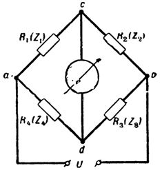
Rice. 2.
If the condition R1R3 = R2R4 is met (respectively, Z1Z3 = Z2Z4 at alternating current), the voltage at the output of the bridge circuit (regardless of the supply voltage) is zero (Ucd = 0), that is, the bridge is "balanced «, which is indicated by a zero pointer .
The steady state of the DC bridge corresponding to the condition R1R3 = R2R4 can be achieved by adjusting only one variable parameter and also allows only one unknown resistance to be determined.
In order to achieve the complex alternating current equilibrium state Z1Z3 = Z2Z4, which decomposes when the complex values of the resistances Z = R + jx are substituted into two independent conditions, at least two variable parameters must be adjusted. In this case, it is possible to simultaneously determine two components of the complex resistance (for example, L and R or L and Q, C and tgφ, etc.).
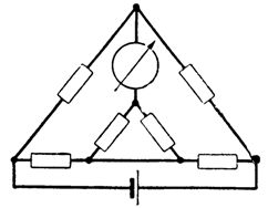
A variety of four-arm AC bridges are resonant bridges... In addition to four-arms, more complex bridge schemes are used - double bridges on direct current (Fig. 3) and multiple arms (six or seven arms) - on alternating current (for example, Fig. 4) . The equilibrium conditions for these circuits, of course, differ from those given above.
Rice. 3.
Rice. 4.
Bridges can be used in both balanced and unbalanced mode. In the latter case, the measurement result is determined without adjusting the resistances, directly from the current or voltage at the output of the bridge circuit, which are functions of the measured resistance and the supply voltage (the latter must be stable). The output device is calibrated directly in the measured value.
AC bridge measurements can be used in two more modes: quasi-balanced and half-balanced. The latter is characterized by the fact that the conventional four-arm circuit (Fig. 2) is adjusted using only one variable parameter until the minimum output voltage is obtained (full equilibrium, i.e. Ucd= 0, which requires the setting of two parameters, in this case it is unreachable).
The moment of reaching the minimum voltage Ucd can be determined directly from a simple pointer at the output of the circuit, or more precisely — indirectly — based on, for example, the phase relations of the voltage vectors of the bridge circuit occurring at the moment of half-equilibrium.
In the second case, the experimental and indicating equipment are similar to those used in the quasi-balanced mode. The components of the measured resistance are determined: one — from the value of the variable parameter at the moment of half-equilibrium, the other — from the bridge output voltage. The supply voltage must be stabilized.
Balancing of measuring bridges can be done both directly by a person (bridges with manual guidance) and with the help of an automatic device (automatic measuring bridges).
Bridge measurements are used both to measure resistance values and to determine the deviations of these values from a given nominal value. They are among the most common and advanced measurement methods. Series-produced bridges have accuracy classes from 0.02 to 5 for DC current and from 0.1 to 5 for AC.