Magnetic circuits of electrical devices
 A magnetic circuit of electrical appliances is called the set of its elements through which the magnetic flux is closed. The magnetic flux in the devices is mainly created by current-streamlined coils, much less often used permanent magnets.
Magnetic system of an electrical product (device) — a part of an electrical product (device), representing a set of ferromagnetic parts designed to conduct the main part of the magnetic flux in it (GOST 18311-80).
The magnetic system, i.e. the combination of the apparatus elements that create the magnetic field consists of two main parts:
1) the core of the electromagnet, which is a fixed part of the electric wire on which the coil is mounted;
2) the movable part of the system, called the armature of the electromagnet.
When an electromagnetic coil is connected to a power source, part of the electricity received by the coil is converted into heat due to energy losses in the resistance of the coil wires, and the remaining energy is used to create a magnetic field.
The magnetic flux passing through the armature creates an electromagnetic force that causes the armature to be attracted to the core. Thus, some of the magnetic energy imparted to the electromagnet coil is converted when the armature is moved into mechanical energy.

Rice. 1. Designation of magnetic circuits of electrical devices
All electromagnetic remote control devices (relays, starters, contactors) work by passing a magnetic flux through their magnetic circuits.
Magnetic systems of devices can be subdivided:
1) By the nature of the current:
a) DC systems
b) AC systems.
2. By way of action:
a) attraction
b) restraint.
Holding systems include, for example, the electromagnetic plates of grinding machines, which are used to magnetically attach the workpieces to be machined. The attraction of electromagnetic devices serves to impart a certain motion to the moving parts of the device.
3. According to the nature of the movement of the armature, magnetic systems are divided into magnets:
a) with translational movement of the anchor
b) with a rotating armature with a rotating movement.
4. According to the method of inclusion, magnetic systems are distinguished by the inclusion of the electromagnetic coil in the supply network in series and in parallel. In the first case, the winding must be designed for the total current determined by the energy receivers and a relatively low voltage. In the second case, the coil is designed to be supplied with full voltage at a relatively low current.
5. The magnetic systems of the devices can have a different mode, operation, which determines the conditions of their heating.As with motors, there are three main modes for devices: continuous, short-term, and intermittent.
6. Electromagnetic systems of devices are also divided according to their design.
In fig. 2 shows the most common designs of vehicle magnetic systems.
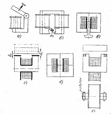
Rice. 2. Forms of magnetic systems of electromagnetic devices
In fig. 2a shows a valve-type solenoid used for both direct and alternating current. When the coil is disconnected from the current source, the armature falls from the core of the electromagnet under the action of the opening spring.
In Fig. 2, b shows the device of a direct current electromagnet with a rotating armature, which tends to settle in a horizontal position, overcoming the resistance of the closing spiral spring. The armor type electromagnet armature shown in fig. 2, c, when switched on, is drawn into the coil.
The electromagnets shown in fig. 2, d and e, are called U-shaped and W-shaped electromagnets. If such an electromagnet is used in electrical appliances with alternating current, its magnetic circuit is made in the form of a set of sheet steel.
Between the armature and the core of the electromagnet, a gasket of non-magnetic material with a thickness of about 0.2 - 0.5 mm is usually installed. This spacer prevents the so-called «magnetic sticking» of the armature to the core when the coil is disconnected from the mains, due to the residual magnetism field. A non-magnetic seal is shown in fig. 2, d.
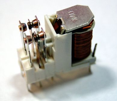
Rice. 3. Electromagnetic relay
Characteristics of the electromagnet clutch so-called dependence of the traction force on the size of the air gap between the anchor and the cores.
Depending on the shape of the magnetic circuit, the type of current feeding the coils, as well as the size of the magnetic gap, the shape of the traction characteristic can be different.