Solid state relays
 The role of reliable switches in modern automation systems is very important. In terms of modern technological fields, such as communication systems, consumer and automotive electronics or industrial automation, everywhere there is a gradual but clear transition from familiar switching schemes to conventional ones. electromagnetic relays and moving contact starters to more reliable switching tools such as solid state relays.
Semiconductors by right replace mechanical switching and control devices even in circuits with powerful current loads, because the process of improving semiconductors every year pleases with higher and higher characteristics of power switches.
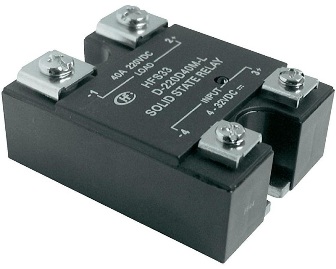
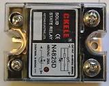
The semiconductor relay contains in its design powerful power switches that successfully replace the contacts of traditional electromagnetic relays, starters and contactors. These advanced solid state relays can switch loads up to 250 amps while being more reliable.
The galvanic isolation of the control and executive circuits does not require additional isolation measures for such a relay. Solid state relays serve as an interface where the low voltage control circuits and the high voltage power circuits are isolated from each other. The structure of solid-state relays from different manufacturers is relatively similar, and all relays of this type have only very small differences.
The input circuit of such a solid-state relay may consist of a resistor in series with an optocoupler, or it may be more complex. The function of the input circuit is to receive a control signal for subsequent switching.
Further down the circuit is optical isolation, which provides isolation between the input, intermediate and output circuits of the solid state relay. The input signal is processed by a trigger circuit that controls the switching of the solid state relay output.
The switching circuit supplies voltage to the load. Usually this part consists of a transistor, thyristor or triac.
For reliable operation of solid-state relays under various conditions, including inductive loads, a protection circuit is required. However, despite the presence of a protective circuit in all solid-state relays, there are still various modifications, and some of these relays do not allow inductive loads, while others are specially adapted for them.
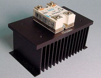
Power semiconductors have some internal resistance, so when the load is switched, the solid-state relay heats up. When heated above 60 degrees Celsius, the permissible value of the switched current decreases, therefore, under severe operating conditions, such a relay requires additional heat dissipation.A radiator or even air cooling is used for this.
For inductive loads, it is recommended to provide a reserve of permissible current 2-4 times, and if we are talking about the control of an asynchronous motor, then the reserve of current should be ten times.
Current voltage when controlling a powerful load of an active nature is eliminated by using a zero-current switching relay, such relays are equipped with an additional trigger circuit control unit that prevents overload starting. But when controlling a load of capacitive or inductive nature, a considerable current margin must be provided.
As a rule, a DC relay with a constant current already has a reserve for a short-term (no more than 10 milliseconds) threefold increase in the rated current when overloaded at start-up, and thyristor relays - tenfold.
For resistance to impulse noise, an RC circuit is installed in a solid relay in parallel with the output circuit, but for more reliable protection, it is necessary to connect external varistors in parallel with each of the phases of such a relay.
The technical documentation provided by the manufacturer, as a rule, contains all the comprehensive data on the characteristics of a particular solid relay and its permissible modes of operation and areas of application in general.