Measuring resistance with a megohmmeter
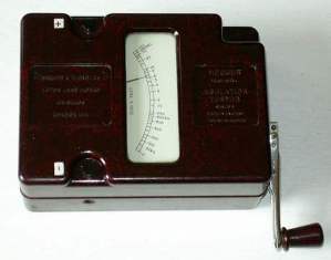
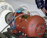 The megohmmeter is designed to measure high resistances, especially insulation resistance. The power source in such devices is an alternator with manual control or a special converter. Unlike other ohmmeters, a voltage of 100, 500, 1000 or 2500 V is generated at the output of the megohmmeter, depending on the device modification or measurement limit.
Here is some information about insulation resistance and the characteristics of its measurement. As you know, electrical insulating materials have a certain conductivity, and therefore, under the action of the applied voltage U, the leakage current passes through the insulation Azs, the equilibrium value of which determines the insulation resistance Ri = U / Ic.
In fig. 1 shows graphs of the changes in insulation resistance Ri and leakage current Азs as a function of the time elapsed after the application of voltage. The current is not established immediately, but after a certain period of time, therefore, the readings of the device should be read no earlier than 60 s.
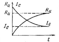
Rice. 1.Plots of changes in insulation resistance and leakage current from time to time
For measurements, you should choose a megohmmeter for the measurement limit and operating voltage. The measuring range of the megohmmeter should be such that the expected insulation resistance is on the right half of its scale (with zero on the left) or on the left half (with zero on the right). The voltage of the megohmmeter is selected depending on the voltage of the network in which the insulation resistance is determined.
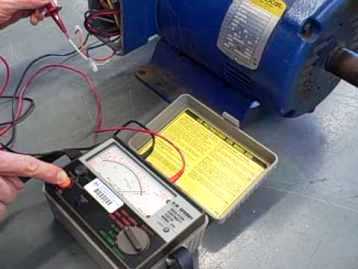
In fig. 2, the megohmmeter connection diagram is shown when measuring the insulation resistance of wire A to the case. To do this, the output of the megohmmeter Z ("ground") is connected to the cable shield or ground wire, and then the output of the megohmmeter L ("line") is connected to the wire.
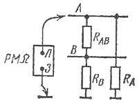
Rice. 2. Connection diagram of a megohmmeter
In this circuit, the device does not measure the insulation resistance RA wires A to ground and the equivalent resistance RNS consisting of two parallel-connected branches: resistance RA and series-connected resistances RB and РАB... Here RB — insulation resistance of conductor B to the ground, RAB — insulation resistance between wires A and B. Therefore, the value of R cannot be determined from the result of a single measurementA, but it can be argued that РАE.
If in the considered circuit it is necessary to establish the resistance RA, then three measurements should be made. In the first measurement wire B is grounded and the megohmmeter is connected to wire A. In this case, the resistance of two parallel resistances RA and РАB is measured.
When wires A and B are closed together and the device is connected to them, the megohmmeter will show the resistance of another pair of resistors RA and РБ... Finally, when wire A is grounded, the measurement will take into account the resistances RB and РАБ.
Mathematically, the measurement results and the resistance RA, RB, RAB are related to each other through the following connections:
RE1 = RA x RB/ (RA+ RB)
RNS2 = RB NS AB/ (RB + RAB)
RNS3 = RA x RAB / (RA + RAB)
If the readings of the megohmmeter are the same in all three cases, then RA = RB = RAB= 2RE1 = 2RE3 = 2RE3
When the readings of the megohmmeter are different, then in order to find RA, RB, Rab, it is necessary to solve the system of equations by substituting the values of RNS, that is, the results of each of the three measurements.
Considering the above, the insulation resistance of the windings of electrical machines and transformers is measured in turn for each of the windings separately, while connecting the other windings to the body of the machine or transformer. This allows you to find the equivalent insulation resistance of a given coil, which includes its insulation resistance to the body and other coils. When measuring, the coil whose insulation resistance is being measured must not be galvanically connected to other coils.
Before starting the measurements, the megohmmeter should be checked. To do this, the terminals of the device are short-circuited and its handle is turned (with a manual drive) or the button in the device with a static transducer is pressed until the arrow of the device is set against the division of the scale with the number 0.
Then short-circuit the clutch and continue to turn the drive handle (press the button). The pointer of the device should be set against the division of. If the device is in good working order, then it can be measured. After measuring the insulation resistance, it is necessary to briefly ground the point to which the wire from the megohmmeter is connected to remove the charge accumulated in the insulation.
Also read on this topic: The procedure for making insulation test measurements with a megohmmeter