Synchronous machines — motors, generators and compensators
 Synchronous machines are alternating current electrical machines in which the rotor and the magnetic field of the stator currents rotate synchronously.
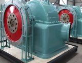
Three-phase synchronous generators are the most powerful electrical machines. The unit power of the synchronous generators at hydroelectric power plants is 640 MW, and at thermal power plants — 8 — 1200 MW. In a synchronous machine, one of the windings is connected to an AC mains and the other is excited by DC. The alternating current winding is called the armature winding.
The armature winding converts all the electromagnetic power of the synchronous machine into electrical power and vice versa. Therefore, it is usually placed on a stator, which is called an armature. The excitation coil consumes 0.3 - 2% of the converted power, therefore it is usually located on a rotating rotor, which is called an inductor, and the low excitation power is supplied by slip rings or non-contact excitation devices.
 The armature magnetic field rotates at a synchronous speed n1 = 60f1 / p, rpm, where p = 1,2,3 … 64, etc. is the number of pole pairs.
With industrial network frequency f1 = 50 Hz, a number of synchronous speeds at different number of poles: 3000, 1500, 1000, etc.). Since the magnetic field of the inductor is stationary relative to the rotor, for the continuous interaction of the fields of the inductor and the armature, the rotor must rotate at the same synchronous speed.
 Construction of synchronous machines
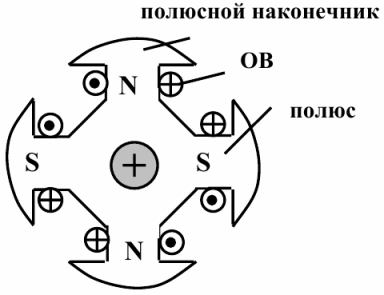
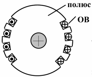
The stator of a synchronous machine with a three-phase winding does not differ in construction asynchronous machine stator, and the rotor with an exciting coil is of two types—prominent pole and implicit pole. At high speeds and a small number of poles, implicit-pole rotors are used because they have a more durable structure, and at low speeds and a large number of poles, salient-pole rotors of modular construction are used. The strength of such rotors is less, but they are easier to manufacture and repair. Apparent Pole Rotor:
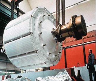
 They are used in synchronous machines with a large number of poles and a correspondingly low n. Hydroelectric plants (hydrogenerators). frequency n from 60 to several hundred revolutions per minute. The most powerful hydrogenerators have a rotor diameter of 12 m with a length of 2.5 m, p — 42 and n = 143 rpm.
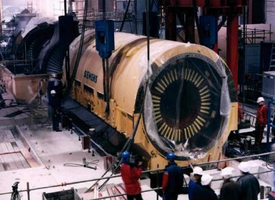
Indirect rotor:
 Winding — diameter d = 1.2 — 1.3 m in the rotor channels, the active length of the rotor is no more than 6.5 m. TPP, NPP (turbine generators). S = 500,000 kVA in one machine n = 3000 or 1500 rpm (1 or 2 pole pairs).
In addition to the field coil, a damper or damping coil is located on the rotor, which is used for starting in synchronous motors. This coil is made similar to a squirrel cage short-circuit coil, only of a much smaller section, since the main volume of the rotor is taken up by the field coil.In non-uniform-pole rotors, the role of the damper winding is played by the surfaces of the solid teeth of the rotor and the conductive wedges in the channels.
Direct current in the excitation winding of a synchronous machine can be supplied from a special DC generator installed on the shaft of the machine and called the exciter, or from the mains through a semiconductor rectifier. 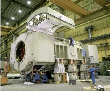 See also on this topic:
Purpose and arrangement of synchronous machines
How synchronous turbos and hydrogenerators work
A synchronous machine can work as a generator or a motor. A synchronous machine can operate as a motor if three-phase mains current is supplied to the stator winding. In this case, as a result of the interaction of the stator and rotor magnetic fields, the stator field carries the rotor with it. In this case, the rotor rotates in the same direction and at the same speed as the stator field.
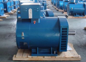
The generator mode of operation of synchronous machines is the most common, and almost all electrical energy is generated by synchronous generators. Synchronous motors are used with power over 600 kW and up to 1 kW as micromotors. Synchronous generators for voltages up to 1000 V are used in units for autonomous power supply systems.
Units with these generators can be stationary and mobile. Most units are used with diesel engines, but they can be powered by gas turbines, electric motors and gasoline engines.
A synchronous motor differs from a synchronous generator only by a starting damping coil, which should ensure good starting properties of the motor.
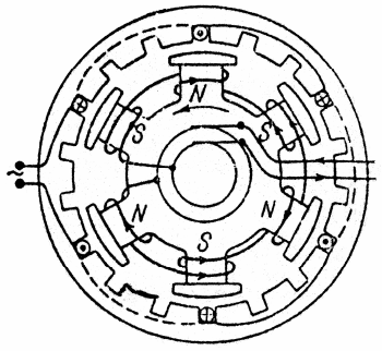
Scheme of a six-pole synchronous generator.Cross-sections of the windings of one phase (three series-connected windings) are shown. The windings of the other two phases fit into the free slots shown in the figure. The phases are connected in star or delta.
Generator mode: the motor (turbine) rotates the rotor, the coil of which is supplied with constant voltage? there is a current that creates a permanent magnetic field. The magnetic field rotates with the rotor, crosses the stator windings and induces an EMF of the same magnitude and frequency but shifted by 1200 (symmetrical three-phase system).
Motor mode: the stator winding is connected to a three-phase network, and the rotor winding to a direct current source. As a result of the interaction of the rotating magnetic field of the machine with the direct current of the excitation coil, a torque Mvr occurs, which drives the rotor to rotate at the speed of the magnetic field.
Mechanical characteristic of a synchronous motor — dependence n (M) — is a horizontal section.
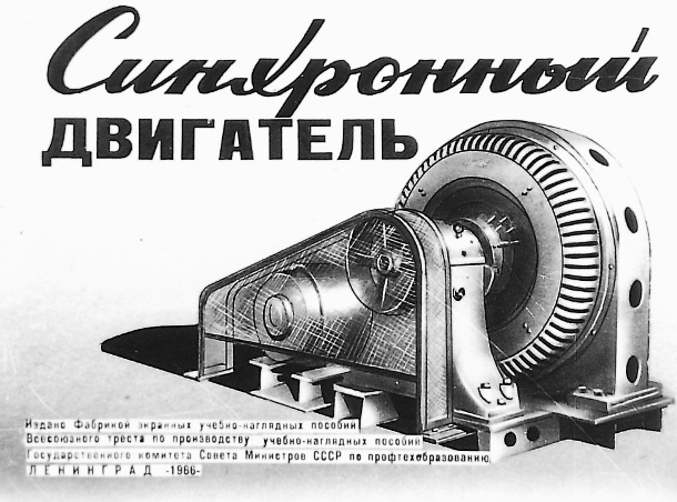
Educational Filmstrip - "Synchronous Motors" produced by the Educational Materials Factory in 1966.
You can watch it here: Filmstrip «Synchronous Motor»
 Application of synchronous motors The mass use of asynchronous motors with a significant underload complicates the operation of power systems and stations: the power factor in the system decreases, which leads to additional losses in all devices and lines, as well as to their insufficient use in terms of active power. Therefore, the use of synchronous motors became necessary, especially for mechanisms with powerful drives.
Synchronous motors have a big advantage over asynchronous motors, which is that, thanks to DC excitation, they can work with cosphi = 1 and do not consume reactive power from the network, and during operation, when overexcited, they even give reactive power to the network. As a result, the power factor of the network is improved and the voltage drop and losses in it are reduced, as well as the power factor of the generators operating in power plants.
The maximum torque of a synchronous motor is proportional to U, and for an asynchronous motor U2.
Therefore, when the voltage drops, the synchronous motor retains a higher load capacity. In addition, the use of the possibility of increasing the excitation current of synchronous motors makes it possible to increase their reliability in case of emergency voltage drops in the network and to improve in these cases the operating conditions of the power system as a whole. Due to the larger size of the air gap, the additional losses in the steel and in the rotor cage of synchronous motors are smaller than those of asynchronous motors, therefore the efficiency of synchronous motors is usually higher.
On the other hand, the construction of synchronous motors is more complicated than squirrel-cage induction motors, and in addition, synchronous motors must have an exciter or other device to supply a DC coil. As a result, synchronous motors are in most cases more expensive than asynchronous squirrel-cage motors.
During the operation of synchronous motors, considerable difficulties arose in starting them.These difficulties have already been overcome.
Starting and speed control of synchronous motors are also more difficult. However, the advantage of synchronous motors is so great that at high powers it is advisable to use them wherever frequent starts and stops and speed control are not required (motor generators, powerful pumps, fans, compressors, mills, crushers and etc.). ).
See also:
Typical schemes for starting synchronous motors
Electromechanical properties of synchronous motors
Synchronous compensators
Synchronous compensators are designed to compensate the power factor of the network and maintain the normal voltage level of the network in areas where consumer loads are concentrated. The overexcited mode of operation of the synchronous compensator is normal when it supplies reactive power to the grid.
In this regard, compensators, as well as capacitor banks that serve the same purposes, installed at consumer substations, are also called reactive power generators. However, in periods of reduced user loads (for example, at night), it is often necessary to use synchronous compensators and in underexcitation mode, when they consume inductive current and reactive power from the network, since in these cases the network voltage tends to increase, and to maintain it at a normal level, it is necessary to load the network with inductive currents, which cause additional voltage drops in it.
For this purpose, each synchronous compensator is equipped with an automatic excitation or voltage regulator, which regulates the magnitude of the excitation current so that the voltage at the terminals of the compensator remains constant.