Inverter welding machines
 The huge interest and peak of popularity that has increased in the last decade in new designs of welding machines working on the principle of inverters is due to the following main reasons:
-
increased seam quality;
-
the availability of operations even for novice welders due to the inclusion of a complex of functions for hot start, anti-sticking of the electrode and arc burning;
-
minimizing the design of welding equipment, ensuring its mobility;
-
significant energy savings compared to transformers.
These advantages became possible due to a change in the approach to the technology of creating a welding arc on an electrode due to the introduction of the latest advances in microprocessor technology.
How are welding inverters
They are powered by 220 V 50 Hz electricity, which comes from a regular electrical outlet. (Apparatus operating in a three-phase network use similar algorithms.) The only limitation you should pay attention to is the power consumption of the apparatus.It must not exceed the rating of the mains protective devices and the conductive properties of the wiring.
The sequence of the five technological cycles used to create a welding arc from the inverter is shown in the photo.
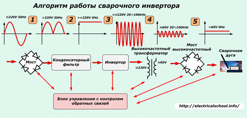
These include processes performed by:
-
rectifier;
-
condenser line filter;
-
high frequency converter;
-
high-frequency voltage step-down transformer;
-
high frequency rectifier;
-
control scheme.
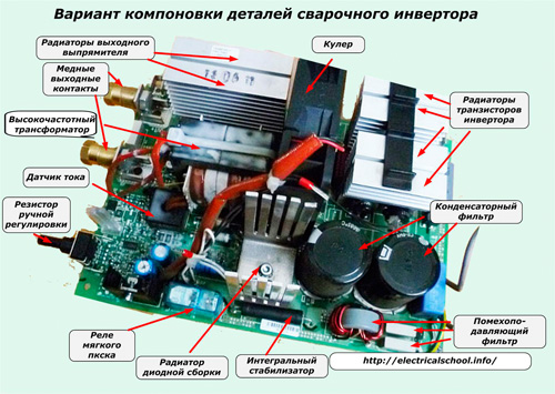
All these devices are located on the board inside the box. With the cover removed they look something like what is shown in the picture.
Mains voltage rectifier
It is supplied with alternating voltage of a stationary electrical network through a manual switch located on the body. It is converted by a diode bridge into a pulsating value. All the energy of the welding arc passes through the semiconductor elements of this block. Therefore, they are selected with the necessary margin of voltage and current.
To improve heat dissipation, the diode assembly, which is subjected to serious heating during operation, is mounted on cooling radiators, which are additionally blown by the supplied air from the fan.
Diode bridge heating is controlled by a temperature sensor set to thermal fuse mode. It, as a protection element, when the diodes are heated to +90 ОC, opens the power circuit.
Condenser line filter
In parallel with the output contact of the rectifier, which creates a ripple voltage, two powerful electrolytic capacitors are connected to work together. They smooth out ripple fluctuations and are always selected with voltage margin.Indeed, even in normal filter mode, it increases by 1.41 times and reaches 220 x 1.41 = 310 volts.
For this reason, capacitors are selected for an operating voltage of at least 400 V. Their capacity is calculated for each structure according to the power of the maximum welding current. Typically it ranges from 470 microfarads or more for a single capacitor.
Interference filter
A working welding inverter converts enough electrical power to cause electromagnetic noise. In this way, it interferes with the rest of the electrical equipment connected to the network. To remove them at the rectifier input, set inductive-capacitive filter.
Its purpose is to smooth out high-frequency disturbances coming from a working circuit to the power network of other electrical consumers.
Inverter
The conversion of direct voltage to high frequency can be done according to different principles.
In welding inverters, two types of circuits operating on the "slanted bridge" principle are most often found:
-
half-bridge half-bridge pulse converter;
-
full-bridge pulse converter.
The figure shows an implementation of the first circuit.
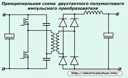
Two powerful transistor switches are used here. They can be assembled on series semiconductor devices MOSFET or IGBT.
Cascade MOSFETs work well in low voltage inverters and also handle welding loads well. For high-capacity fast charge/discharge, they need a push driver with anti-phase signal control to fast charge capacitors with one transistor and short to ground to discharge with another.
Bipolar IGBTs are gaining popularity in welding inverters.They can easily transmit large powers with high voltages, but require more complex control algorithms.
The scheme of a half-bridge pulse converter is found in the constructions of welding inverters of the middle price category. It has good efficiency, it is reliable, it forms a transformer rectangular pulses with a high frequency of several tens of kHz.
The full bridge pulse converter is more complex, it includes two additional transistors.
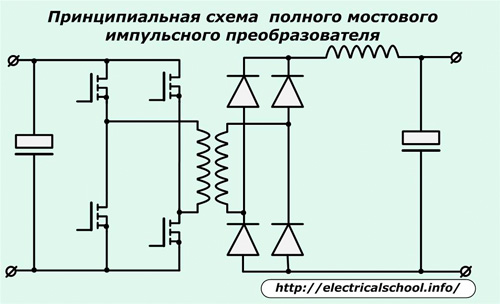
It takes full advantage of all the possibilities of a high-frequency transformer with transistor switches operating in pairs in the mode of two combined slant bridges.
This circuit is used in the most powerful and expensive welding inverters.
All key transistors are installed on powerful heatsinks to remove heat. In addition, they are further protected from possible voltage spikes by damping RC filters.
High frequency transformer
This is a special transformer structure, usually of a ferrite magnetic circuit, which steps down the high-frequency voltage after the inverter with minimal losses to a stable arc ignition of about 60 — 70 volts.
Large welding currents of up to several hundred amperes flow in its secondary winding. Thus, when converting vol. / H energy with a relatively low value of current and high voltage in the secondary winding, welding currents are formed with already reduced voltage.
Due to the use of high frequency and the transition to a ferrite magnetic circuit, the weight and dimensions of the transformer itself are significantly reduced, power losses due to reversal of iron magnetism are reduced and efficiency is increased.
For example, a welding transformer of an old design with an iron magnetic core, providing a welding current of 160 amperes, weighs about 18 kg, and a high-frequency one (with the same electrical characteristics) is slightly less than 0.3 kilograms.
The advantages in the weight of the device and, accordingly, in the working conditions are obvious.
Power output rectifier
It is based on a bridge assembled from special high-speed, very high-speed diodes capable of responding to high-frequency current — opening and closing with a recovery time of about 50 nanoseconds.
Conventional diodes cannot cope with this task. The duration of their transient corresponds to about half the period of the sinusoidal harmonic of the current, or about 0.01 seconds. Because of this, they quickly heat up and burn.
The power diode bridge, like the transistors of the high-voltage transformer, is placed on the heat sinks and protected by a damping RC circuit against voltage spikes.
The output terminals of the rectifier are made with thick copper lugs for a secure connection of the welding cables to the electrode circuit.
Characteristics of the control scheme
All operations of the welding inverter are controlled and controlled by the processor through feedback using various sensors. This provides almost ideal welding current parameters for joining all types of metals.
Thanks to precisely dosed loads, energy losses during welding are significantly reduced.
To operate the control circuit, a constant stabilized voltage is supplied from the power supply, which is internally connected to the 220 V input circuits.This tension is aimed at:
-
cooling fan for radiators and boards;
-
soft start relay;
-
LED indicators;
-
power supply to the microprocessor and operational amplifier.
Relay for soft start inverter is clear from the name. It works on the following principle: at the moment of switching on the inverter, the electrolytic capacitors of the network filter begin to charge very sharply. Their charging current is very high and can damage the rectifier diodes.
To prevent this, the charge is limited by a powerful resistor, which with its active resistance reduces the initial inrush current. When the capacitors are charged and the inverter starts operating in the design mode, the soft start relay activates and through its normally open contacts manipulates this resistor, thereby removing it from the stabilization circuits.
Almost all inverter logic is enclosed inside the microprocessor controller. It controls the operation of the powerful transistors of the converter.
Overvoltage protection of gate and emitter power transistors is based on the use of zener diodes.
A sensor is connected to the winding circuit of the high-frequency transformer - a current transformer, which with its secondary circuits sends a signal proportional in magnitude and angle for logic processing. In this way, the strength of the welding currents is controlled to affect them during start-up and operation of the inverter.
To control the magnitude of the input voltage at the input of the mains rectifier of the apparatus, an operational amplifier microcircuit is connected.It constantly analyzes the signals from the voltage and current protection, determining the moment of an emergency situation when it is necessary to block the operating generator and disconnect the inverter from the power supply.
Maximum deviations of the supply voltage are controlled by a comparator. It is triggered when critical energy values are reached. Its signal is sequentially processed by logic elements to turn off the generator and the inverter itself.
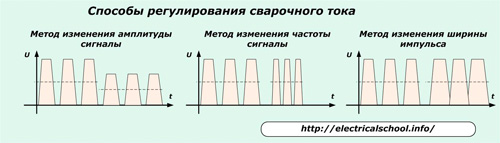
For manual adjustment of the current of the welding arc, an adjusting potentiometer is used, the knob of which is brought out to the body of the device. Changing its resistance allows one of the control methods to be used, affecting:
-
amplitude in / h voltage of the inverter;
-
frequency of high-frequency pulses;
-
pulse duration.
Basic rules of operation and causes of failures of welding inverters
Respect for complex electronic equipment is always the key to its long-term and reliable operation. But, unfortunately, not all users apply this provision in practice.
Welding inverters work in production workshops, on construction sites or are used by home craftsmen in personal garages or summer cottages.
In a production environment, inverters most often suffer from dust that collects inside the box. Its sources can be any tools or metalworking machines, processing metals, concrete, granite, bricks. This is especially common when working with grinders, bricklayers, perforators...
The next reason for the failure that occurred during welding is the creation of non-standard loads on the electronic circuit by an inexperienced welder.For example, if you try to cut the frontal armor of a tank tower or railway rail with a low-power welding inverter, the result of such work is unequivocally predictable: burning of IGBT or MOSFET electronic components.
Inside the control circuit, a thermal relay works, which protects against gradually increasing thermal loads, but it will not have time to react to such rapid jumps in welding currents.
Each welding inverter is characterized by the «PV» parameter - the duration of switching on compared to the duration of the stop pause, which is indicated in the technical passport. Failure to follow these plant recommendations leads to inevitable crashes.
Careless treatment of the device can be expressed in its poor transportation or transportation, when the body is exposed to external mechanical shocks or vibrations of the frame of a moving car.
Among the employees, there are cases of operation of inverters with obvious signs of malfunctions that require immediate removal, for example, loosening of the contacts that fix the welding cables in the sockets of the housing. And handing over expensive equipment to unskilled and poorly trained personnel also usually leads to accidents.
At home, supply voltage drops often occur, especially in garage cooperatives, and the welder does not pay attention to this and tries to do his work faster, "squeezing" everything that he is capable and incapable of from the inverter ...
Winter storage of expensive electronic equipment in a poorly heated garage or even in a shed leads to the deposition of condensate from the air on the boards, oxidation of contacts, damage to tracks and other internal damage.Likewise, these devices suffer from operation in low temperatures below -15 degrees or atmospheric precipitation.
Transferring the inverter to a neighbor for welding work does not always end with a favorable result.
However, the general statistics of workshops show that for private owners, welding equipment works longer and better.
Design flaws
Welding inverters from older versions are lower in reliability welding transformers… And their modern design, especially of IGBT modules, already has comparable parameters.
During the welding process, a large amount of heat is generated inside the housing. The system used to remove and cool circuit boards and electronic elements in even mid-range models is not very efficient. Therefore, during operation, it is necessary to observe interruptions to reduce the temperature of internal parts and devices.
Like all electronic circuits, inverter devices lose their functionality with high humidity and condensation.
Despite the inclusion of noise-removal filters in the design, quite significant high-frequency interference penetrates the power circuit. Technical solutions that eliminate this problem significantly complicate the device, which leads to a sharp increase in the price of all equipment.