Power transformers — device and principle of operation
When transporting electricity over long distances, the principle of transformation is used to reduce losses. For this purpose, the electricity generated by the generators is fed to the transformer substation. It increases the amplitude of the voltage entering the power line.
The other end of the transmission line is connected to the input of the remote substation. On it, the voltage is reduced to distribute the electricity between consumers.
In both substations, special power supply devices are involved in the transformation of high-power electricity:
1. transformers;
2. autotransformers.
They have many common features and characteristics, but differ in certain principles of operation. This article describes only the first designs where the transfer of electricity between individual coils is due to electromagnetic induction. In this case, current and voltage harmonics varying in amplitude preserve the oscillation frequency.
Transformers are used to convert low voltage alternating current to a higher voltage (step-up transformers) or a higher voltage to a lower voltage (step-down transformers). The most widespread are the power transformers for general application for transmission lines and distribution networks. Power transformers in most cases are built as three-phase current transformers.
Device characteristics
Power transformers in electricity are installed on pre-prepared stationary sites with strong foundations. Tracks and rollers can be installed to place on the ground.
A general view of one of the many types of power transformers working with 110/10 kV voltage systems and with a total power of 10 MVA is shown in the picture below.
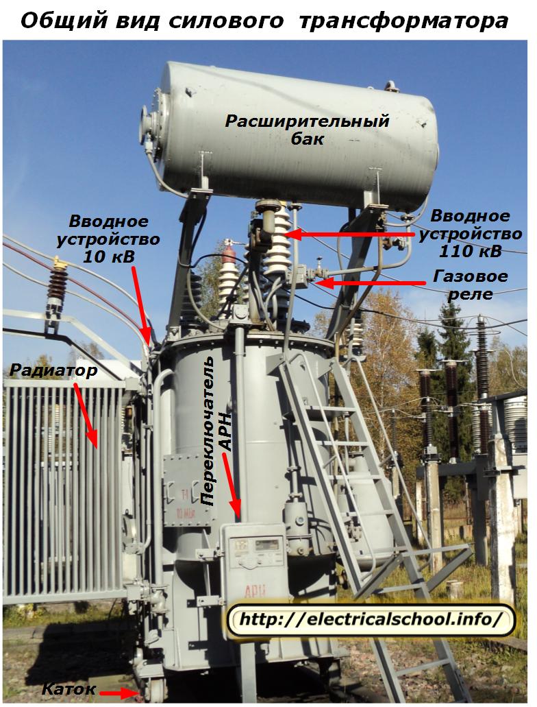
Some individual elements of its construction are provided with signatures. In more detail, the arrangement of the main parts and their mutual arrangement is shown in the drawing.
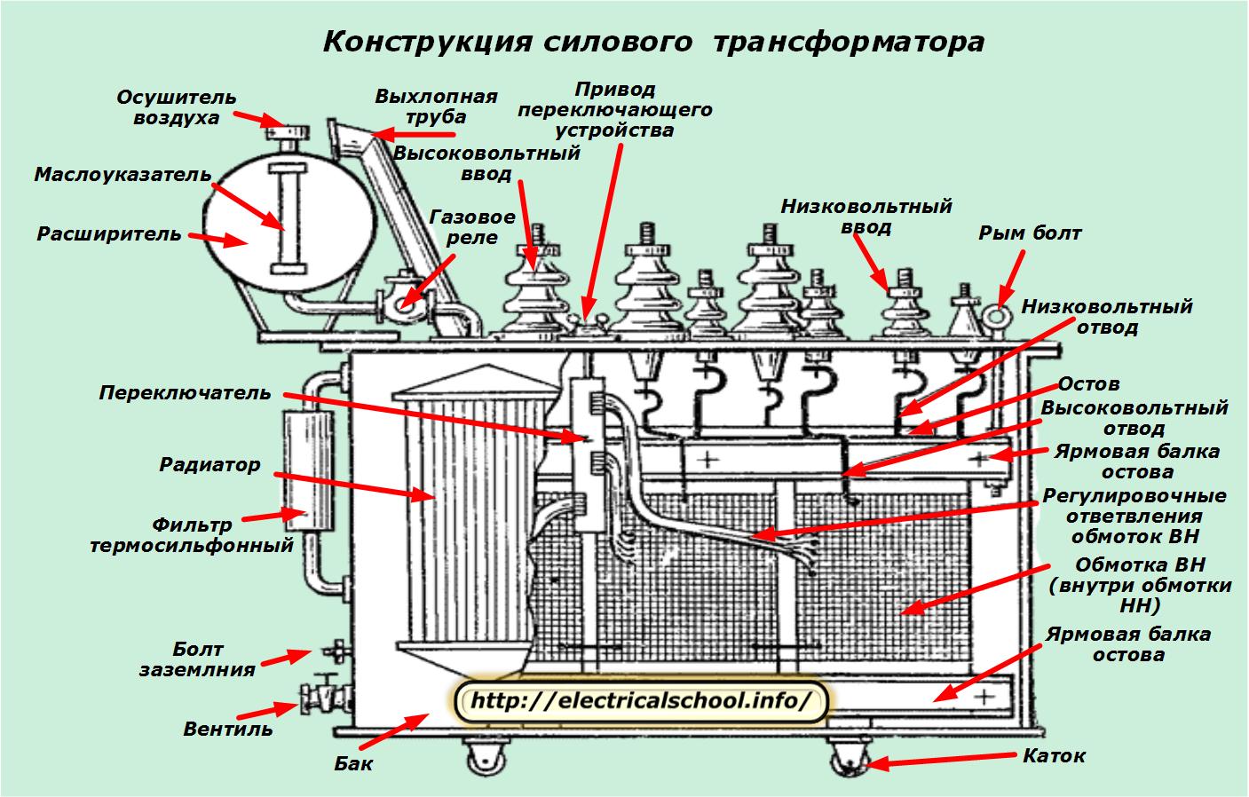
A core 9 is installed inside the tank, on which the windings with low voltage windings 11 and high voltage 10 are placed. The front wall of the transformer is 8. The terminals of the high voltage winding are connected to the inputs passing through porcelain insulators 2.
The windings for the low voltage winding are also connected to the wires passing through the insulators 3.The cover is attached to the upper edge of the tank and a rubber gasket is placed between them to prevent oil from leaking into the joint between the tank and the cover. Two rows of holes are drilled in the wall of the tank, thin-walled pipes 7 are welded into them, through which oil flows.
On the cover there is a knob 1. By turning it, you can switch the turns of the high voltage coil to adjust the voltage under load. Clamps are welded to the cover, on which a tank 5, called an expander, is mounted.
It has an indicator 4 with a glass tube for monitoring the oil level and a plug with a filter 6 for communication with the surrounding air. The transformer moves on rollers 12, the axes of which pass through the beams welded to the bottom of the tank.
When large currents flow, the transformer windings are subjected to forces that tend to deform them. To increase the strength of the windings, they are wound on insulating cylinders. If a square strip is placed in a circle, then the area of the circle is not fully used. Therefore, the transformer rods are made with a stepped cross-section by assembling from sheets of different widths.
Hydraulic diagram of the transformer
The picture shows a simplified composition and interaction of its main elements.
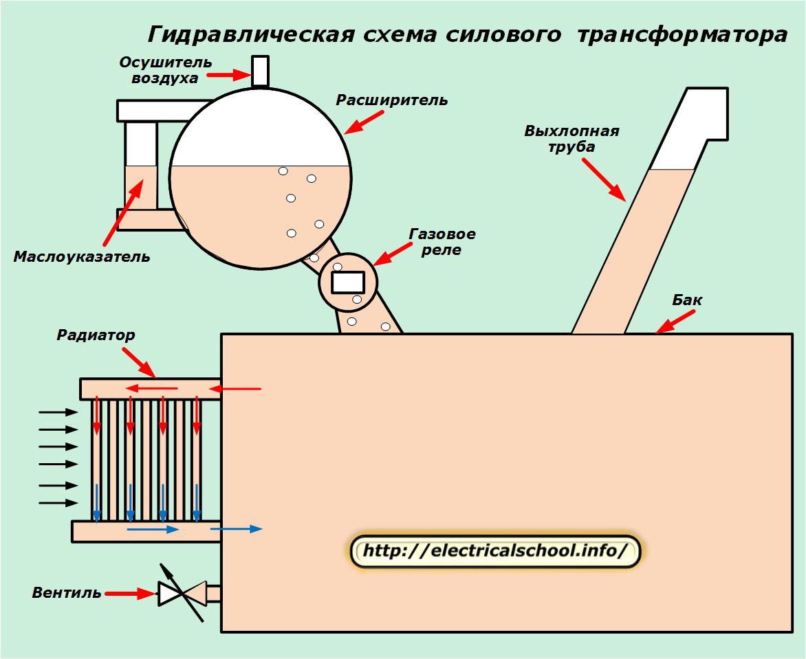
Special valves and a screw are used to fill / drain oil, and the shut-off valve located at the bottom of the tank is designed to take oil samples and then carry out its chemical analysis.
Principles of cooling
The power transformer has two oil circulation circuits:
1. external;
2. internal.
The first circuit is represented by a radiator consisting of upper and lower collectors connected by a system of metal pipes. Heated oil passes through them, which, being in the refrigerant lines, cools and returns to the tank.
Oil circulation in the tank can be done:
-
in a natural way;
-
forced due to the creation of pressure in the system by pumps.
Often, the surface of the tank is increased by creating corrugations — special metal plates that improve heat transfer between the oil and the surrounding atmosphere.
The intake of heat from the radiator to the atmosphere can be carried out by blowing the system by fans or without them due to free air convection. Forced airflow effectively increases heat removal from the equipment, but increases energy consumption to operate the system. They can reduce load characteristic of the transformer up to 25%.
The thermal energy released by modern high-power transformers reaches enormous values. Its size can be attributed to the fact that now, at its expense, they began to implement projects for heating industrial buildings located next to constantly operating transformers. They maintain optimal operating conditions of the equipment, even in winter.
Oil level control in the transformer
The reliable operation of the transformer depends to a large extent on the quality of the oil with which its tank is filled. In operation, two types of insulating oil are distinguished: pure dry oil, which is poured into the tank, and working oil, which is in the tank during operation of the transformer.
The specification of the transformer oil determines its viscosity, acidity, stability, ash, content of mechanical impurities, flash point, pour point, transparency.
Any abnormal operating conditions of the transformer immediately affect the quality of oil, therefore its control is very important in the operation of transformers. Communicating with air, the oil is moistened and oxidized. Moisture can be removed from the oil by cleaning with a centrifuge or filter press.
Acidity and other violations of technical properties can be removed only by regenerating the oil in special devices.
Internal transformer failures such as winding defects, insulation failure, local heating or "fire in the iron" etc. lead to changes in oil quality.
The oil is continuously circulated in the tank. Its temperature depends on a whole complex of influencing factors. Therefore, its volume changes all the time, but is maintained within certain limits. An expansion tank is used to compensate for volume deviations of the oil. It is convenient to monitor the current level in it.
An oil indicator is used for this. The simplest devices are made according to the scheme of communication vessels with a transparent wall, pre-graded in units of volume.
Connecting such a pressure gauge in parallel with the expansion tank is sufficient to monitor the operation. In practice, there are other oil indicators that differ from this principle of action.
Protection against moisture penetration
Since the upper part of the expansion tank is in contact with the atmosphere, an air dryer is installed in it, which prevents moisture from penetrating the oil and reduces its dielectric properties.
Internal damage protection
It is an important element of the oil system gas relay… It is installed inside the piping connecting the main transformer tank to the expansion tank. Therefore, all gases released when heated by the oil and organic insulation pass through the container with the sensitive element of the gas relay.
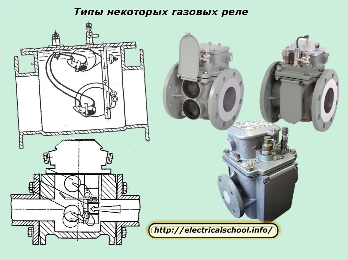
This sensor is set from operation for a very small, allowable gas formation, but is triggered when it increases in two stages:
1. to issue a light / sound warning signal to the service personnel for the occurrence of a malfunction when the set value of the first value is reached;
2. to turn off the power breakers on all sides of the transformer to release the voltage in case of violent gassing, which indicates the beginning of powerful processes of decomposition of oil and organic insulation, which start with short circuits inside the tank.
An additional function of the gas relay is to monitor the oil level in the transformer tank. When it drops to a critical value, the gas protection can work depending on the setting:
-
signal only;
-
to switch off with a signal.
Protection against emergency pressure build-up inside the tank
The drain pipe is mounted on the cover of the transformer in such a way that its lower end communicates with the capacity of the tank, and the oil flows inside to the level in the expander. The upper part of the tube rises above the expander and retracts to the side, slightly bent down.Its end is hermetically sealed by a glass safety membrane, which breaks in the event of an emergency increase in pressure due to the occurrence of undefined heating.
Another design of such protection is based on the installation of valve elements that open when the pressure increases and close when they are released.
Another type is siphon protection. It is based on the rapid compression of the wings with a sharp rise in the gas. As a result, the lock that holds the arrow, which in its normal position is under the influence of a compressed spring, is knocked down. The released arrow breaks the glass membrane and thus relieves the pressure.
Power transformer connection diagram
Inside the tank housing are located:
-
skeleton with upper and lower beam;
-
magnetic circuit;
-
high and low voltage coils;
-
adjustment of winding branches;
-
low and high voltage taps
-
the bottom of the high and low voltage bushings.
The frame, together with the beams, serves to mechanically fasten all the components.
Interior design
The magnetic circuit serves to reduce the losses of the magnetic flux passing through the coils. It is made from grades of electrical steel using the laminated method.
The load current flows through the phase windings of the transformer. Metals are chosen as materials for their production: copper or aluminum with a round or rectangular section. Special brands of cable paper or cotton yarn are used to insulate the turns.
In concentric windings used in power transformers, a low voltage (LV) winding is usually placed on the core, which is surrounded by a high voltage (HV) winding on the outside.This arrangement of the windings, firstly, makes it possible to move the high-voltage winding from the core, and secondly, it facilitates access to the high-voltage windings during repairs.
For better cooling of the coils, channels formed by insulating spacers and gaskets between the coils are left between them. The oil circulates through these channels, which, when heated, rise and then descend through the pipes of the tank, in which they are cooled.
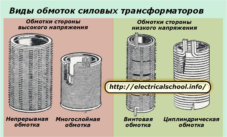
Concentric coils are wound in the form of cylinders located one inside the other. For the high-voltage side, a continuous or multi-layer winding is created, and for the low-voltage side, a spiral and cylindrical winding.
The LV winding is placed closer to the rod: this makes it easier to make a layer for its insulation. Then a special cylinder is mounted on it, providing isolation between the high and low voltage sides, and the HV winding is mounted on it.
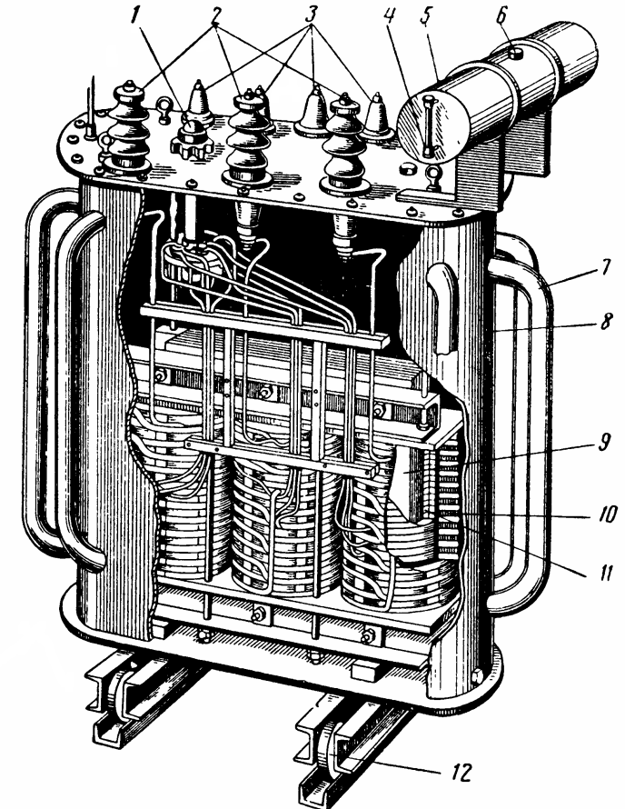
The installation method described is shown on the left side of the picture below, with the concentric arrangement of the transformer rod windings.
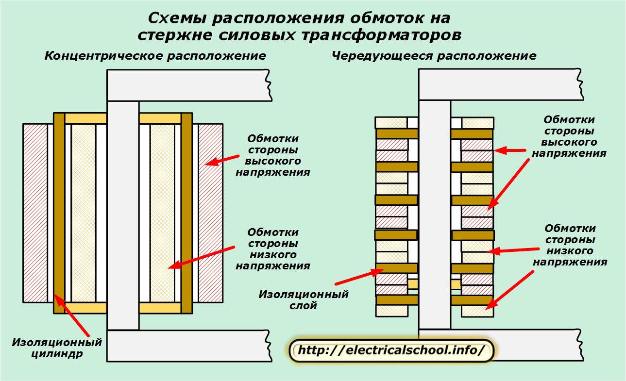
The right side of the picture shows how alternate windings are placed, separated by an insulating layer.
In order to increase the electrical and mechanical strength of the insulation of the windings, their surface is impregnated with a special type of glyphthalic varnish.
To connect the windings on one side of the voltage, the following circuits are used:
-
stars;
-
triangle;
-
zig-zag.
In this case, the ends of each coil are marked with letters of the Latin alphabet, as shown in the table.
Transformer type Winding side Low voltage Medium voltage High voltage Start end neutral Start end neutral Start end neutral Single-phase a x — At Ht — A x — Two windings three phases a NS 0 — — — A x 0 b Y B Y with G ° C Z Three windings three phases a x At Ht A x b Y 0 YT 0 B Y 0 ° С Z Ht ° С Z
The terminals of the windings are connected to the corresponding down conductors which are mounted on the bushing insulator bolts located on the transformer tank cover.
In order to realize the possibility of adjusting the value of the output voltage, branches are made on the windings. One of the variants of the control branches is shown in the diagram.
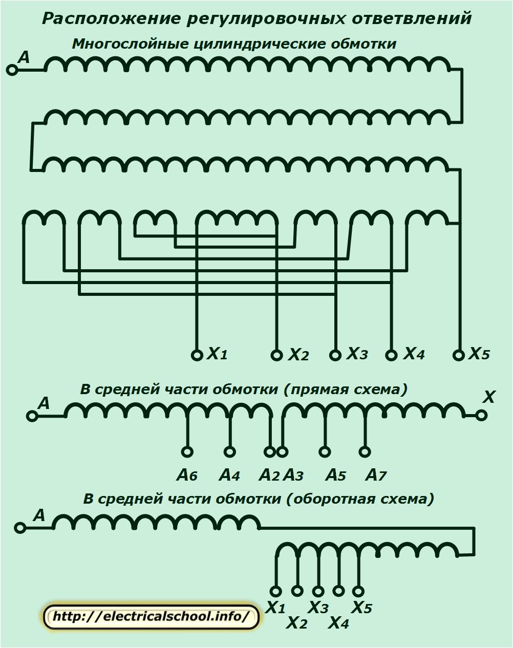
The voltage regulation system is designed with the ability to change the nominal value within ± 5%. To do this, complete five steps of 2.5% each.
For high-power power transformers, regulation is usually created on a high-voltage winding. This simplifies the design of the tap switch and allows to improve the accuracy of the output characteristics by providing more turns on that side.
In multi-layer cylindrical coils, the regulating branches are made on the outside of the layer at the end of the coil and are located symmetrically at the same height relative to the yoke.
For individual projects of transformers, branches are made in the middle part. When using a reverse circuit, one half of the winding is done with the right coil and the other with the left coil.
A three-phase switch is used to switch the taps.
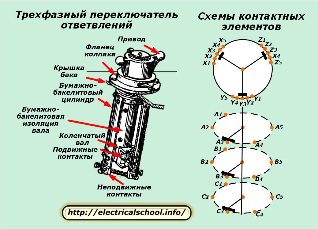
It has a system of fixed contacts, which are connected to the branches of the coils, and movable ones, which switch the circuit, creating different electric circuits with fixed contacts.
If the branches are made near the zero point, then one switch controls the operation of all three phases at once. This can be done because the voltage between the individual parts of the switch does not exceed 10% of the linear value.
When taps are made in the middle part of the winding, then its own, individual switch is used for each phase.
Methods of adjusting the output voltage
There are two types of switches that allow you to change the number of turns on each coil:
1. with load reduction;
2. under load.
The first method takes longer to complete and is not popular.
Load switching enables easier management of electrical networks by providing uninterrupted power to connected consumers. But to do it, you need to have a complex design of the switch, which is equipped with additional functions:
-
performing transitions between branches without interruption of load currents by connecting two adjacent contacts during switching;
-
limiting the short-circuit current inside the winding between the connected taps during their simultaneous switching on.
The technical solution to these problems is the creation of switching devices operated by remote control, using current-limiting reactors and resistors.
In the photo shown at the beginning of the article, the power transformer uses automatic adjustment of the output voltage under load by creating an AVR design that combines a relay circuit to control an electric motor with an actuator and contactors.
Principle and modes of operation
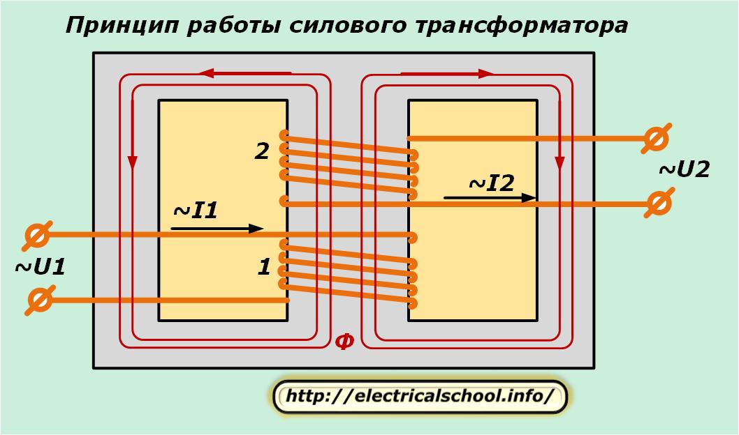
The operation of a power transformer is based on the same laws as in a conventional one:
-
An electric current passing through the input coil with a time-varying harmonic of the oscillations induces a changing magnetic field inside the magnetic circuit.
-
The changing magnetic flux penetrating the turns of the second coil induces an EMF in them.
Modes of operation
During operation and testing, the power transformer may be in operating or emergency mode.
Mode of operation created by connecting a voltage source to the primary winding and the load to the secondary. In this case, the value of the current in the windings should not exceed the calculated permissible values. In this mode, the power transformer must supply all consumers connected to it for a long time and reliably.
A variant of the operating mode is the no-load and short-circuit tests to check the electrical characteristics.
No-load created by opening the secondary circuit to shut off the flow of current in it. It is used to determine:
-
Efficiency;
-
transformation factor;
-
losses in the steel due to core magnetization.
A short-circuit attempt is created by short-circuiting the terminals of the secondary winding, but with an underestimated voltage at the input of the transformer to a value capable of creating a secondary rated current without exceeding it.This method is used to determine copper losses.
To emergency modes, a transformer includes any violations of its operation, leading to a deviation of the operating parameters outside the limits of their permissible values. A short circuit inside the windings is considered particularly dangerous.
Emergency modes lead to fires of electrical equipment and the development of irreversible consequences. They are capable of causing massive damage to the power system.
Therefore, in order to prevent such situations, all power transformers are equipped with automatic, protective and signaling devices, which are designed to maintain the normal operation of the primary loop and quickly disconnect it from all sides in the event of a malfunction.