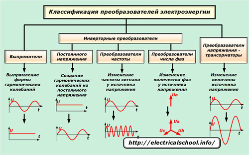
Types of electrical energy conversion
 A huge number of household appliances and industrial installations in their work are powered by electrical energy of different types. It is created by multitude EMF and current sources.
Generator sets produce single-phase or three-phase current at industrial frequency, while chemical sources produce direct current. At the same time, in practice, situations often arise when one type of electricity is not enough for the operation of certain devices and it is necessary to carry out its conversion.
For this purpose, the industry produces a large number of electrical devices that work with different parameters of electrical energy, converting them from one type to another with different voltages, frequency, number of phases and waveforms. According to the functions they perform, they are divided into conversion devices:
-
simple;
-
with the ability to adjust the output signal;
-
endowed with the ability to stabilize.
Classification methods
By the nature of the operations performed, converters are divided into devices:
-
standing up
-
reversal of one or more stages;
-
changes in signal frequency;
-
conversion of the number of phases of the electrical system;
-
changing the voltage type.
According to the control methods of the emerging algorithms, adjustable converters work on:
-
the pulse principle used in DC circuits;
-
phase method used in harmonic oscillator circuits.
The simplest converter designs may not be equipped with a control function.
All conversion devices can use one of the following circuit types:
-
pavement;
-
zero;
-
with or without a transformer;
-
with one, two, three or more phases.
Corrective devices
This is the most common and old class of converters that allow you to get rectified or stabilized direct current from an alternating sinusoidal, usually industrial frequency.
Rare exhibits
Low power devices
Only a few decades ago, selenium structures and vacuum-based devices were still used in radio engineering and electronic devices.
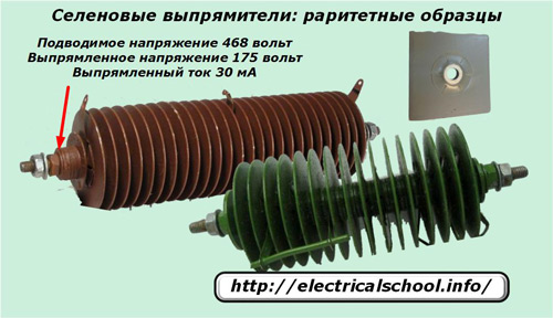
Such devices are based on the principle of current correction from a single element of a selenium plate. They were sequentially assembled into a single structure by mounting adapters. The higher the voltage required for correction, the more such elements are used. They were not very powerful and could withstand a load of several tens of milliamps.
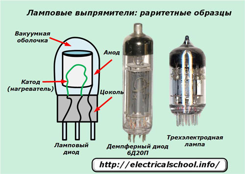
A vacuum was created in the sealed glass housing of the lamp rectifiers. It houses electrodes: an anode and a cathode with a filament, which ensure the flow of thermionic radiation.
Such lamps provided direct current power for various circuits of radio receivers and televisions until the end of the last century.
Ignitrons are powerful devices
In industrial devices, anode-cathode mercury ion devices operating on the controlled arc charge principle have been widely used in the past. They were used where it was necessary to operate a DC load with a strength of hundreds of amperes at a rectified voltage up to and including five kilovolts.
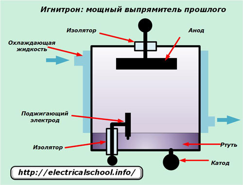
Electron flow was used for current flow from the cathode to the anode. It is created by an arcing discharge caused in one or more areas of the cathode, called luminous cathode spots. They are formed when the auxiliary arc is turned on by the ignition electrode until the main arc ignites.
For this, short-term pulses of a few milliseconds with a current strength of up to tens of amperes were created. Changing the shape and strength of the pulses made it possible to control the operation of the igniter.
This design provides good voltage support during rectification and fairly high efficiency. But the technical complexity of the design and difficulties in operation led to the rejection of its use.
Semiconductor devices
Diodes
Their work is based on the principle of current conduction in one direction due to the properties of the p-n junction formed by contacts between semiconductor materials or metal and semiconductor.
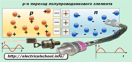
Diodes only pass current in a certain direction, and when an alternating sinusoidal harmonic passes through them, they cut off one half-wave and are therefore widely used as rectifiers.
Modern diodes are produced in a very wide range and are endowed with various technical characteristics.
Thyristors
The thyristor uses four conductive layers that form a more complex semiconductor structure than a diode with three series-connected p-n junctions J1, J2, J3. The contacts with the outer layer «p» and «n» are used as anode and cathode, and with the inner layer as the control electrode of the UE, which is used to switch the thyristor into action and perform regulation.
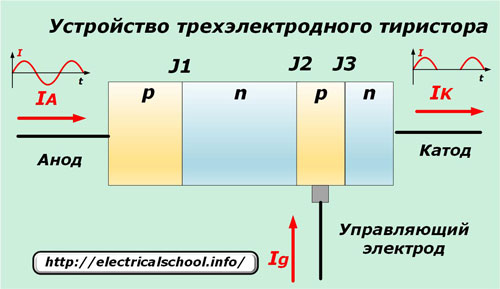
The rectification of a sinusoidal harmonic is carried out on the same principle as for a semiconductor diode. But in order for the thyristor to work, it is necessary to take into account a certain characteristic — the structure of its internal transitions must be open for the passage of electric charges, and not closed.
This is done by passing a current of a certain polarity through the driving electrode. The photo below shows the ways to open the thyristor used simultaneously to adjust the amount of current passed at different times.
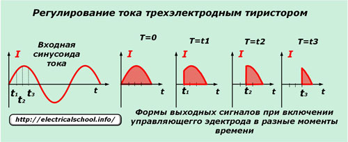
When the current is applied through RE at the moment of passing the sinusoid through the zero value, a maximum value is created, which gradually decreases at points «1», «2», «3».
In this way, the current is adjusted along with the thyristor regulation. Triacs and power MOSFETs and/or AGBTs in power circuits work in a similar way. But they do not perform the function of correcting the current, passing it in both directions. Therefore, their control schemes use an additional pulse interrupt algorithm.
DC / DC converters
These designs do the opposite of rectifiers. They are used to generate alternating sinusoidal current from direct current obtained from chemical current sources.
A rare development
Since the late 19th century, electrical machine structures have been used to convert direct voltage into alternating voltage. They consist of a direct current electric motor which is powered by a battery or battery pack and an AC generator whose armature is rotated by the motor drive.
In some devices, the generator winding was wound directly on the common rotor of the motor. This method not only changes the shape of the signal, but also, as a rule, increases the amplitude or frequency of the voltage.
If three windings located at 120 degrees are wound on the armature of the generator, then with its help an equivalent symmetrical three-phase voltage is obtained.
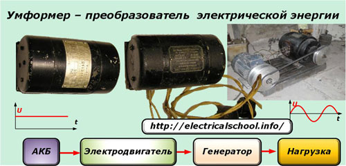
Umformers were widely used until the 1970s for radio lamps, equipment for trolleybuses, trams, electric locomotives before the mass introduction of semiconductor elements.
Inverter converters
Operating principle
As a basis for consideration, we take the KU202 thyristor test circuit from a battery and a light bulb.
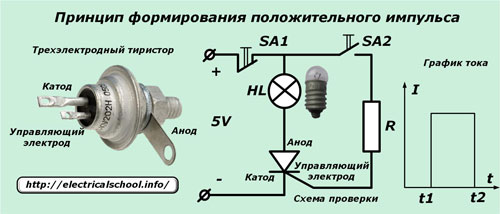
A normally closed contact of the SA1 button and a low power filament lamp are built into the circuit to supply the positive potential of the battery to the anode. The control electrode is connected through a current limiter and an open contact of the SA2 button. The cathode is firmly connected to the negative of the battery.
If at time t1 you press the button SA2, the current will flow to the cathode through the circuit of the control electrode, which will open the thyristor and the lamp included in the anode branch will light up. Due to the design features of this thyristor, it will continue to burn even when contact SA2 is open.
Now at time t2 we press button SA1.The supply circuit of the anode will turn off and the light will go out due to the fact that the flow of current through it stops.
The graph of the presented picture shows that a direct current passed through the time interval t1 ÷ t2. If you switch the buttons very quickly, then you can form rectangular pulse with a positive sign. Similarly, you can create a negative impulse. For this purpose, it is enough to change the circuit slightly to allow the current to flow in the opposite direction.
A sequence of two pulses with positive and negative values creates a waveform called a square wave in electrical engineering. Its rectangular shape roughly resembles a sine wave with two half-waves of opposite signs.
If in the scheme under consideration we replace the buttons SA1 and SA2 with relay contacts or transistor switches and switch them according to a certain algorithm, then it will be possible to automatically create a meander-shaped current and adjust it to a certain frequency, duty cycle, period. Such switching is controlled by a special electronic control circuit.
Block diagram of the power supply section
As an example, consider the simplest primary system of a bridge inverter.
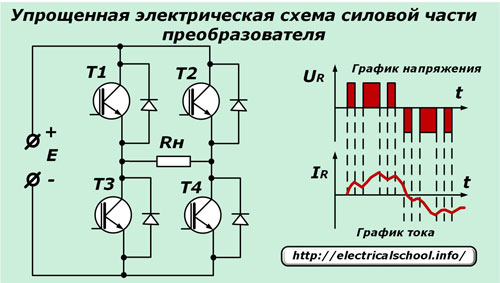
Here, instead of a thyristor, specially selected field transistor switches deal with the formation of a rectangular pulse. The load resistance Rn is included in the diagonal of their bridge. The supply electrodes of each transistor «source» and «drain» are oppositely connected with shunt diodes, and the output contacts of the control circuit are connected to the «gate».
Due to the automatic operation of the control signals, voltage pulses of different duration and sign are output to the load. Their sequence and characteristics are tailored to the optimal parameters of the output signal.
Under the action of the applied voltages on the diagonal resistance, taking into account the transient processes, a current arises, the shape of which is already closer to a sinusoid than that of a meander.
Difficulties in technical implementation
For the good functioning of the power circuit of the inverters, it is necessary to ensure the reliable operation of the control system, which is based on switching switches. They are endowed with bilateral conducting properties and are formed by shunting transistors by connecting reverse diodes.
To adjust the amplitude of the output voltage, it is most often used pulse width modulation principle by selecting the pulse area of each half-wave by the method of controlling its duration. In addition to this method, there are devices that work with pulse-amplitude conversion.
In the process of forming the circuits of the output voltage, a violation of the symmetry of the half waves occurs, which adversely affects the operation of inductive loads. This is most noticeable with transformers.
During the operation of the control system, an algorithm is set for generating the keys of the power circuit, which includes three stages:
1. straight;
2. short circuit;
3. vice versa.
In the load, not only pulsating currents are possible, but also currents changing in direction, which create additional disturbances at the source terminals.
Typical design
Among the many different technological solutions used to create inverters, three schemes are common, considered from the point of view of the degree of increase in complexity:
1. bridge without transformer;
2. with the neutral terminal of the transformer;
3. bridge with transformer.
Output waveforms
Inverters are designed to supply voltage:
-
rectangular;
-
trapezoid;
-
stepped alternating signals;
-
sinusoids.
Phase converters
Industry produces electric motors to operate under specific operating conditions, taking into account power from certain types of sources. However, in practice, situations arise when, for various reasons, it is necessary to connect a three-phase asynchronous motor to a single-phase network. Various electrical circuits and devices have been developed for this purpose.
Energy-intensive technologies
The stator of a three-phase asynchronous motor includes three windings that are wound in a certain way, located 120 degrees from each other, each of which, when the current of its voltage phase is applied to it, creates its own rotating magnetic field. The direction of the currents is chosen so that their magnetic fluxes complement each other, providing mutual action for the rotation of the rotor.
When there is only one phase of the supply voltage for such a motor, it becomes necessary to form three current circuits from it, each of which is also shifted by 120 degrees. Otherwise, the rotation will not work or will be defective.
In electrical engineering, there are two simple ways to rotate the current vector relative to the voltage by connecting to:
1. inductive load when the current starts to lag the voltage by 90 degrees;
2.Ability to create a current conductor of 90 degrees.
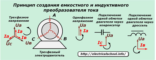
The above photo shows that from one phase of the voltage Ua you can get a current shifted at an angle not by 120, but only by 90 degrees forward or backward. In addition, this will also require selecting the capacitor and choke ratings to produce an acceptable motor operating mode.
In the practical solutions of such schemes, they most often stop at the capacitor method without the use of inductive resistances. For this purpose, the voltage of the supply phase was applied to one coil without any transformations, and to the other, shifted by capacitors. The result was acceptable torque for the engine.
But in order to turn the rotor, it was necessary to create an additional torque by connecting the third winding through starting capacitors. It is impossible to use them for constant operation due to the formation of large currents in the starting circuit, which quickly create increased heating. Therefore, this circuit was switched on briefly to gain the moment of inertia of the rotor rotation.
Such schemes were easier to implement due to the simple formation of capacitor banks of specified values from individual available elements. However, the chokes had to be calculated and wound independently, which is difficult to do not only at home.
However, the best conditions for the operation of the motor were created with the complex connection of the capacitor and choke in different phases with the selection of the directions of the currents in the windings and the use of current-suppressing resistors. With this method, the loss of engine power was up to 30%.However, the designs of such converters are not economically profitable, since they consume more electricity for operation than the motor itself.
The capacitor start circuit also consumes an increased rate of electricity, but to a lesser extent. In addition, the motor connected to its circuit is capable of generating power just over 50% of that which is created with a normal three-phase supply.
Due to the difficulties in connecting a three-phase motor to a single-phase supply circuit and the large losses of electrical and output power, such converters have shown their low efficiency, although they continue to work in individual installations and metal-cutting machines.
Inverter devices
Semiconductor elements made it possible to create more rational phase converters produced on an industrial basis. Their designs are usually designed to operate in three-phase circuits, but they can be designed to operate with a large number of strings located at different angles.
When the converters are powered by one phase, the following sequence of technological operations is performed:
1. rectification of single-phase voltage by a diode node;
2. smoothing of the waves from the stabilization circuit;
3. conversion of direct voltage to three-phase due to the inversion method.
In this case, the supply circuit can consist of three single-phase parts working autonomously, as discussed earlier, or one common one, assembled, for example, according to an autonomous three-phase inverter conversion system using a neutral common conductor.
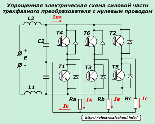
Here, each phase load operates its own pairs of semiconductor elements, which are controlled by a common control system. They create sinusoidal currents in the phases of the resistances Ra, Rb, Rc, which are connected to the common supply circuit through the neutral wire. It adds the current vectors from each load.
The quality of the approximation of the output signal to a pure sine wave shape depends on the overall design and complexity of the circuit used.
Frequency converters
On the basis of inverters, devices have been created that allow changing the frequency of sinusoidal oscillations in a wide range. For this purpose, the 50 hertz electricity supplied to them undergoes the following changes:
-
standing up
-
stabilization;
-
high frequency voltage conversion.
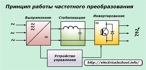
The work is based on the same principles of the previous projects, except that the control system based on microprocessor boards generates an output voltage with an increased frequency of tens of kilohertz at the output of the converter.
Frequency conversion based on automatic devices allows you to optimally adjust the operation of electric motors at the time of starting, stopping and reversing, and it is convenient to change the speed of the rotor. At the same time, the harmful impact of transients in the external power network is sharply reduced.
Read more about it here: Frequency converter - types, principle of operation, connection schemes
Welding inverters
The main purpose of these voltage converters is to maintain stable arc burning and easy control of all its characteristics, including ignition.
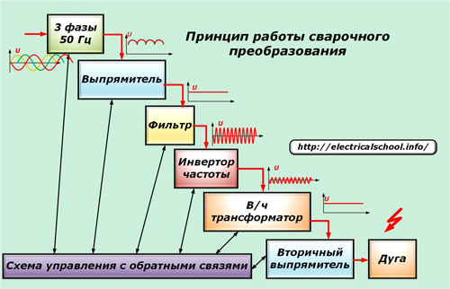
For this purpose, several blocks are included in the design of the inverter, which perform sequential execution:
-
correction of three-phase or single-phase voltage;
-
stabilization of parameters through filters;
-
inversion of high-frequency signals from stabilized DC voltage;
-
conversion to / h voltage by a step-down transformer to increase the value of the welding current;
-
secondary adjustment of output voltage for welding arc formation.
Due to the use of high-frequency signal conversion, the dimensions of the welding transformer are greatly reduced and materials are saved for the entire structure. Welding inverters have great advantages in operation compared to their electromechanical counterparts.
Transformers: voltage converters
In electrical engineering and energy, transformers operating on the electromagnetic principle are still most widely used to change the amplitude of the voltage signal.
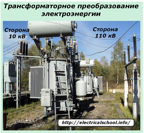
They have two or more coils and magnetic circuit, through which magnetic energy is transmitted to convert the input voltage into an output voltage of altered amplitude.