How do AC and DC generators work?
The term "generation" in electrical engineering comes from the Latin language. It means "birth". Regarding energy, we can say that generators are technical devices that generate electricity.
In this case, it should be noted that electric current can be produced by converting different types of energy, for example:
-
chemical;
-
light;
-
thermal and others.
Historically, generators are structures that convert the kinetic energy of rotation into electricity.
According to the type of electricity generated, the generators are:
1. direct current;
2. variable.
The principle of operation of the simplest generator
The physical laws that make it possible to create modern electrical installations for generating electricity by transforming mechanical energy were discovered by the scientists Oersted and Faraday.
Any generator design applies principle of electromagnetic inductionwhen there is an induction of an electric current in a closed frame due to its intersection with a rotating magnetic field that is created permanent magnets in simplified models for home use or excitation coils on industrial products with increased power.
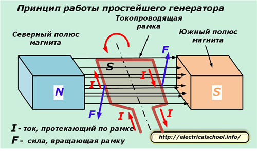
When you rotate the bezel, the magnitude of the magnetic flux changes.
The electromotive force induced in the loop depends on the rate of change of the magnetic flux penetrating the loop in a closed loop S and is directly proportional to its value. The faster the rotor spins, the higher the voltage generated.
In order to create a closed loop and divert electric current from it, it was necessary to create a collector and a brush that provides constant contact between the rotating frame and a stationary part of the circuit.
Due to the construction of spring-loaded brushes pressed against the collector plates, the electric current is transmitted to the output terminals and from them passes to the consumer's network.
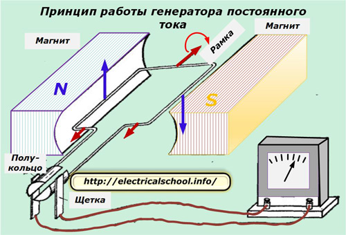
The principle of operation of the simplest DC generator
As the frame rotates around the axis, its left and right halves cycle around the south or north poles of the magnets. Each time in them there is a change in the direction of the currents in the reverse, so that at each pole they flow in one direction.
To create a direct current in the output circuit, a half-ring is created at the collector node for each half of the coil. Brushes adjacent to the ring remove the potential only of their sign: positive or negative.
Since the semi-ring of the rotating frame is open, moments are created in it when the current reaches its maximum value or is absent. In order to maintain not only the direction, but also a constant value of the generated voltage, the frame is made according to a specially prepared technology:
-
it uses not one coil, but several — depending on the magnitude of the planned voltage;
-
the number of frames is not limited to one copy: they try to make a sufficient number to optimally maintain the voltage drop at the same level.
In the DC generator, the rotor windings are located in the slots magnetic circuit… This allows to reduce the loss of the induced electromagnetic field.
Design features of DC generators
The main elements of the device are:
-
external power frame;
-
magnetic poles;
-
stator;
-
rotating rotor;
-
switch block with brushes.
Frame made of steel alloys or cast iron to give mechanical strength to the overall structure. An additional task of the housing is to transfer the magnetic flux between the poles.
Poles of magnets attached to the body with pins or bolts. A coil is mounted on them.
A stator, also called a yoke or skeleton, is made of ferromagnetic materials. The coil of the excitation coil is placed on it. Stator core equipped with magnetic poles forming its magnetic field.
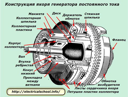
Rotor has a synonym: anchor. Its magnetic core consists of laminated plates that reduce the formation of eddy currents and increase efficiency. The rotor and/or self-excitation windings are laid in the core channels.
A switching node with brushes, it can have a different number of poles, but is always a multiple of two. The brush material is usually graphite. The collector plates are made of copper, as the most optimal metal suitable for the electrical properties of current conduction.
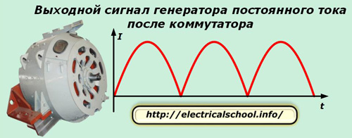
Thanks to the use of a switch, a pulsating signal is generated at the output terminals of the DC generator.
The main types of constructions of DC generators
According to the type of power supply of the excitation coil, devices are distinguished:
1. with self-excitation;
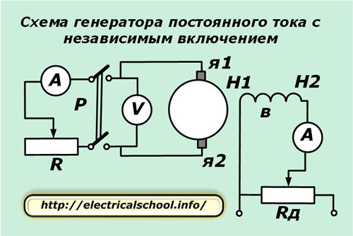
2. operating on the basis of independent inclusion.
The first products can:
-
use permanent magnets;
-
or operate from external sources, eg batteries, wind turbines...
Independently switched generators operate from their own winding, which can be connected:
-
sequentially;
-
shunts or parallel excitation.
One of the options for such a connection is shown in the diagram.
An example of a DC generator is a design that was often used in automotive engineering in the past. Its structure is the same as that of an induction motor.
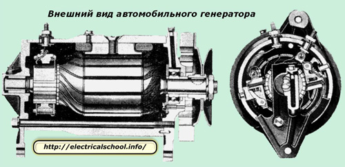
Such collector structures can operate simultaneously in engine or generator mode. Because of this, they have become widespread in existing hybrid vehicles.
Anchor formation process
This occurs in idle mode when the brush pressure is incorrectly adjusted, creating a suboptimal friction mode. This can lead to a reduction in magnetic fields or a fire due to increased sparking.
The ways to reduce are:
-
compensation of magnetic fields by connecting additional poles;
-
adjustment of the offset of the position of the collector brushes.
Advantages of DC generators
They include:
-
without losses due to hysteresis and eddy current formation;
-
work in extreme conditions;
-
reduced weight and small dimensions.
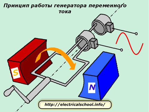
The principle of operation of the simplest alternator
Inside this design, the same details are used as in the previous analogue:
-
magnetic field;
-
rotating frame;
-
collector block with current drain brushes.
The main difference lies in the design of the collector assembly, which is designed so that when the frame rotates through the brushes, contact is constantly made with half of the frame without cyclically changing their position.
Therefore, the current, which changes according to the laws of harmonics in each half, is transferred completely unchanged to the brushes, and then through them to the consumer circuit.
Naturally, the frame is created by winding not from one turn, but a calculated number of them to achieve the optimal tension.
Thus, the principle of operation of DC and AC generators is common, and the design differences are in the production of:
-
rotating rotor collector assembly;
-
rotor winding configuration.
Design features of industrial alternators
Consider the main parts of an industrial induction generator in which the rotor receives rotational motion from a nearby turbine. The stator construction includes an electromagnet (although the magnetic field can be created by a set of permanent magnets) and a rotor winding with a certain number of turns.
An electromotive force is induced in each loop, which is successively added in each of them and forms at the output terminals the total value of the voltage supplied to the supply circuit of the connected consumers.
To increase the amplitude of the EMF at the output of the generator, a special design of the magnetic system is used, made of two magnetic circuits due to the use of special grades of electrical steel in the form of laminated plates with channels. Coils are installed inside them.
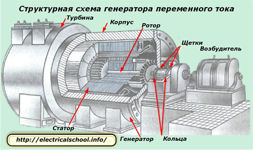
In the generator housing, there is a stator core with channels to accommodate a coil that creates a magnetic field.
The rotor rotating on bearings also has a slotted magnetic circuit inside which is mounted a coil that receives an induced EMF. Usually, the horizontal direction is chosen for the axis of rotation, although there are generators with a vertical arrangement and the corresponding design of the bearings.
A gap is always created between the stator and the rotor, which is necessary to ensure rotation and prevent jamming. But at the same time, there is a loss of magnetic induction energy in it. Therefore, they try to make it as small as possible, taking into account both requirements in an optimal way.
Located on the same shaft as the rotor, the exciter is a relatively low power direct current generator. Its purpose: to supply electricity to the windings of a power generator in a state of independent excitation.
Such exciters are most often used with turbine or hydraulic generator designs when creating a primary or backup method of excitation.
The photo of an industrial generator shows the arrangement of slip rings and brushes to capture currents from a rotating rotor structure. During operation, this device is subjected to constant mechanical and electrical stress. To overcome them, a complex structure is created, which during operation requires periodic checks and preventive measures.
To reduce the operating costs generated, a different, alternative technology is used that also uses the interaction between rotating electromagnetic fields. Only permanent or electric magnets are placed on the rotor and the voltage is removed from the stationary coil.
When creating such a circuit, such a structure can be called the term «alternator». It is used in synchronous generators: high frequency, automotive, diesel locomotives and ships, power plant installations for the production of electricity.
Characteristics of synchronous generators
Operating principle
The name and distinctive feature of the action lies in the creation of a rigid connection between the frequency of the alternating electromotive force induced in the stator winding «f» and the rotation of the rotor.
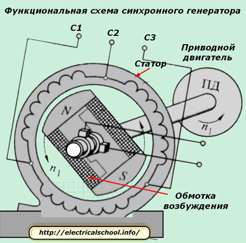
A three-phase winding is mounted in the stator, and on the rotor there is an electromagnet with a core and an exciting winding fed by DC circuits through a brush collector.
The rotor is driven into rotation by a source of mechanical energy — a drive motor at the same speed. Its magnetic field makes the same motion.
Electromotive forces of the same magnitude but shifted by 120 degrees in direction are induced in the stator windings, creating a three-phase symmetrical system.
When they are connected to the ends of the windings of consumer circuits, phase currents begin to act in the circuit, which form a magnetic field rotating in the same way: synchronously.
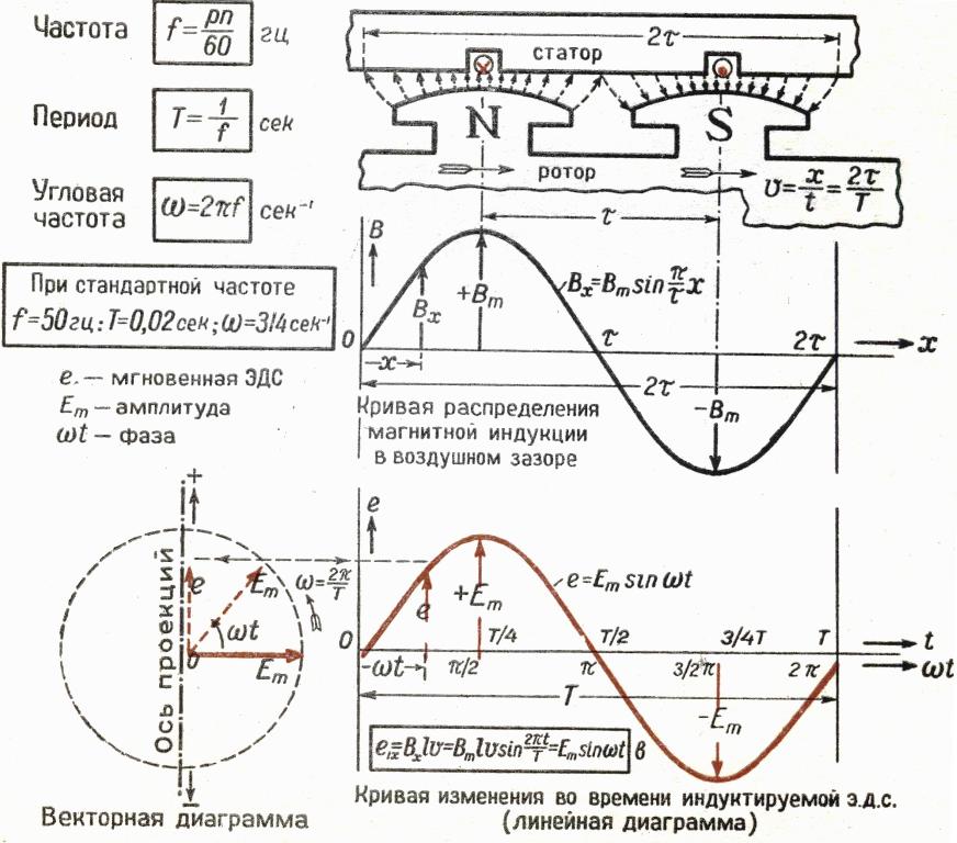
The form of the output signal of the induced EMF depends only on the distribution law of the magnetic induction vector in the gap between the rotor poles and the stator plates. Therefore, they seek to create such a design when the magnitude of the induction changes according to a sinusoidal law.
When the gap is constant, the flow vector inside the gap is trapezoidal, as shown in line graph 1.
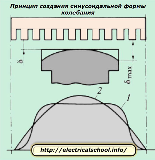
However, if the shape of the fringes at the poles is corrected to be skewed by changing the gap to the maximum value, then it is possible to achieve a sinusoidal shape of the distribution as shown in line 2. This technique is used in practice.
Excitation circuits for synchronous generators
The magnetomotive force arising on the excitation winding of the rotor «OB» creates its magnetic field. For this there are different DC exciter designs based on:
1. method of contact;
2. non-contact method.
In the first case, a separate generator called exciter «B» is used. Its excitation coil is powered by an additional generator according to the principle of parallel excitation, called a «PV» exciter.
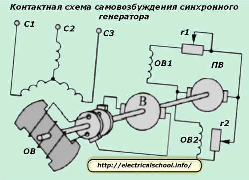
All rotors are located on a common shaft. Therefore, they rotate in exactly the same way. Rheostats r1 and r2 are used to regulate the currents in the excitation and amplifier circuits.
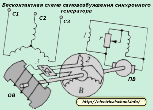
With the non-contact method, there are no slip rings on the rotor. A three-phase exciter winding is mounted directly on it. It rotates synchronously with the rotor and transmits electric direct current through the co-rotating rectifier directly to the exciter winding «B».
The types of contactless circuits are:
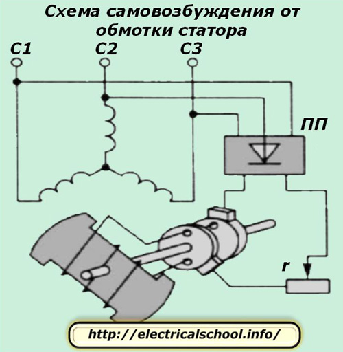
1. self-excitation system from the stator's own winding;
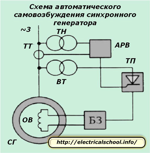
2. automated scheme.
In the first method, the voltage from the stator windings is fed to the step-down transformer, and then to the semiconductor rectifier «PP», which generates direct current.
With this method, the initial excitation is created due to the phenomenon of residual magnetism.
The automatic scheme for creating self-excitation involves the use of:
-
voltage transformer VT;
-
automated excitation regulator ATS;
-
current transformer TT;
-
rectifier VT;
-
thyristor converter TP;
-
protection block BZ.
Characteristics of asynchronous generators
The main difference between these designs is the lack of a rigid relationship between the rotor speed (nr) and the EMF induced in the coil (n). There is always a difference between them, which is called "slip". It is denoted by the Latin letter "S" and is expressed by the formula S = (n-nr) / n.
When the load is connected to the generator, a braking torque is created to turn the rotor. It affects the frequency of the generated EMF, creates a negative slip.
The construction of the rotor for asynchronous generators is made:
-
short circuit;
-
phase;
-
hollow.
Asynchronous generators can have:
1. independent excitement;
2. self-excitation.
In the first case, an external AC voltage source is used, and in the second, semiconductor converters or capacitors are used in the primary, secondary or both types of circuits.
Thus, alternators and direct current generators have much in common in the principles of construction, but differ in the design of certain elements.